When installaing a new desktop machine with Ubuntu 24.04 I came across a situation when booting where there was a 30 second delay at the GRUB OS select screen.
This is not something that I was wanting for a new OS, so I looked for a method to sorten or eliminate it.
The normal method is to run `sudo nano /etc/default/grub`. Change the `GRUB_TIMEOUT=30` line to something more appropriate then run `sudo upate-grub` and you're good. However..... my file had `GRUB_TIMEOUT=0`.
After a few Google searches I discovered that my problem appears to be an artifact of the type of file system I set up (ZFS) when installing the OS.
If GRUB decides that the boot media it is looking at is not writable or that it lacks write support for the filesystem being used it is not able to record that the boot worked so it assumes it failed and generates the boot menu lines. The reported filesystems it doesn't like are
btrfs
cpiofs
newc
odc
romfs
squash4
tarfs
zfs
diskfilter
lvm
There's ZFS <sigh>.
So. I could go back to EXT4, which I really don't want to do because I'm a modern progressive sort of person who wants to be in with the cool kids. So...
I added `GRUB_RECORDFAIL_TIMEOUT=3` to /etc/default/grub (of course you can modify it to your desired value). Save the file and run `sudo update-grub`.
When I ran `sudo update-grub` I recieved a warning that (amongst other things) os-prober will not be executed to detect other bootable partitions. I'm okay with that.
A Doppler sensor is a device that transmits a high frequency RF signal and listens for the reflected signal that bounces off nearby objects. That reflected signal will vary in frequency from the transmitted signal if the object it bounces off is moving. This is due to the Doppler effect. The sensor detects the difference in the frequency of the transmitted and reflected signal and produces an output signal when the amount of movement exceeds a specific threshold.
The Doppler Effect
The Doppler effect is named after Christian Doppler who was an Austrian physicist that described the effect in the 1800s. The most common example that most people have experienced is when a car or a train sounding its horn moves towards and then past us. While the car/train is moving towards us the pitch of the horn is high and as it passes us the pitch changes to a lower tone.
Of course some will instantly recognise the effect from the costume worn by Jim Parsons as the character ‘Sheldon Cooper’ in the episode of CBS’s comedy, ‘The Big Bang Theory’ titled ‘The Middle Earth Paradigm’.
Sheldon Cooper as the Doppler Effect
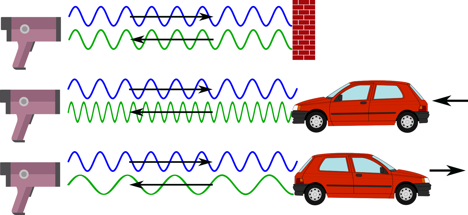
This is also the technique used by police forces to determine the speed of motorists on the road. A speed camera or ‘radar gun’ emits a specific Radio Frequency (RF) and since the Doppler effect will make any reflected frequency lower if the car is moving away from the speed camera or higher if the car is moving towards the speed camera, measuring the frequency difference between the emitted signal and the reflected signal can determine the speed of the vehicle.
Radar Gun Frequency Comparison
How does a Microwave Doppler Sensor Work?
A microwave Doppler sensor starts with an electronic device called an ‘oscillator’. This device will set the frequency of operation for the unit and allows the transmitter to broadcast a specific frequency from a built in transmitting / receiving antenna. Once broadcast, the signals reflect off the surroundings and are then returned to the sensor and collected by a receiver on the board. This reflected signal will vary in frequency (according to the Doppler effect) if any of the objects that the signal bounced off were moving towards or away from the transmitter. This received signal is then mixed with the original oscillator frequency. The mixing process will produce a difference frequency that is the difference between the original oscillator and the reflected signals.
So when our sensor sees a difference frequency of significant strength, it knows that there has been something moving close by and can generate a signal to represent it.
The RWCL-0516 Microwave Radar Sensor
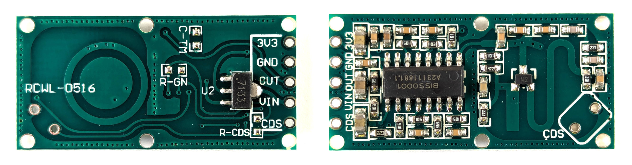
The sensor that we will use is a very simple device that can take an input voltage of between 4 and 28V. With this it will generate a frequency using an oscillator of around 3.182GHz. The oscillator includes an inductor and capacitor that are formed by the copper etched into the board itself. We can see these as the concentric circles on one side and the ‘S’ shape on the other.
Both Sides of RWCL-0516
The transmitted frequency is not particularly directional, so anything moving around the unit out to a maximum distance of between 5 to 7 meters can be detected. In fact, because the signal is high enough, it will pass through some semi-solid objects (such as a covering container).
Once movement has been detected an output pin is set to ‘high’ for 2 seconds to identify that there has been a trigger.
The RWCL-0516 has five pins as follows
3v3 - This is a 3.3v output that can be used for powering other devices (Just to be clear. This is NOT the connection point to power the RWCL-0516).
GND - The ground reference point
OUT - This is the output pin that will indicate movement when it occurs.
VIN - This is where our input voltage is applied (between 4 to 28V).
CDS - This pin will allow us to disable an optional light sensor on the board (we won’t be fitting this in our example)
The board also has the provision to add components that can adjust the function of the unit.
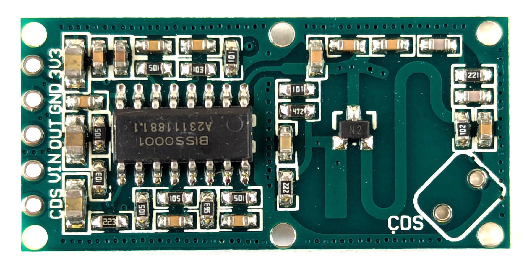
On the front side of the board (the side with the majority of the components) there is a space labelled CDS. This is short for ‘Cadmium DiSulphide’. This is the location where a Light Dependant Resister (LDR) can be added to disable the board when there is sufficient light.
Front of the RWCL-0516
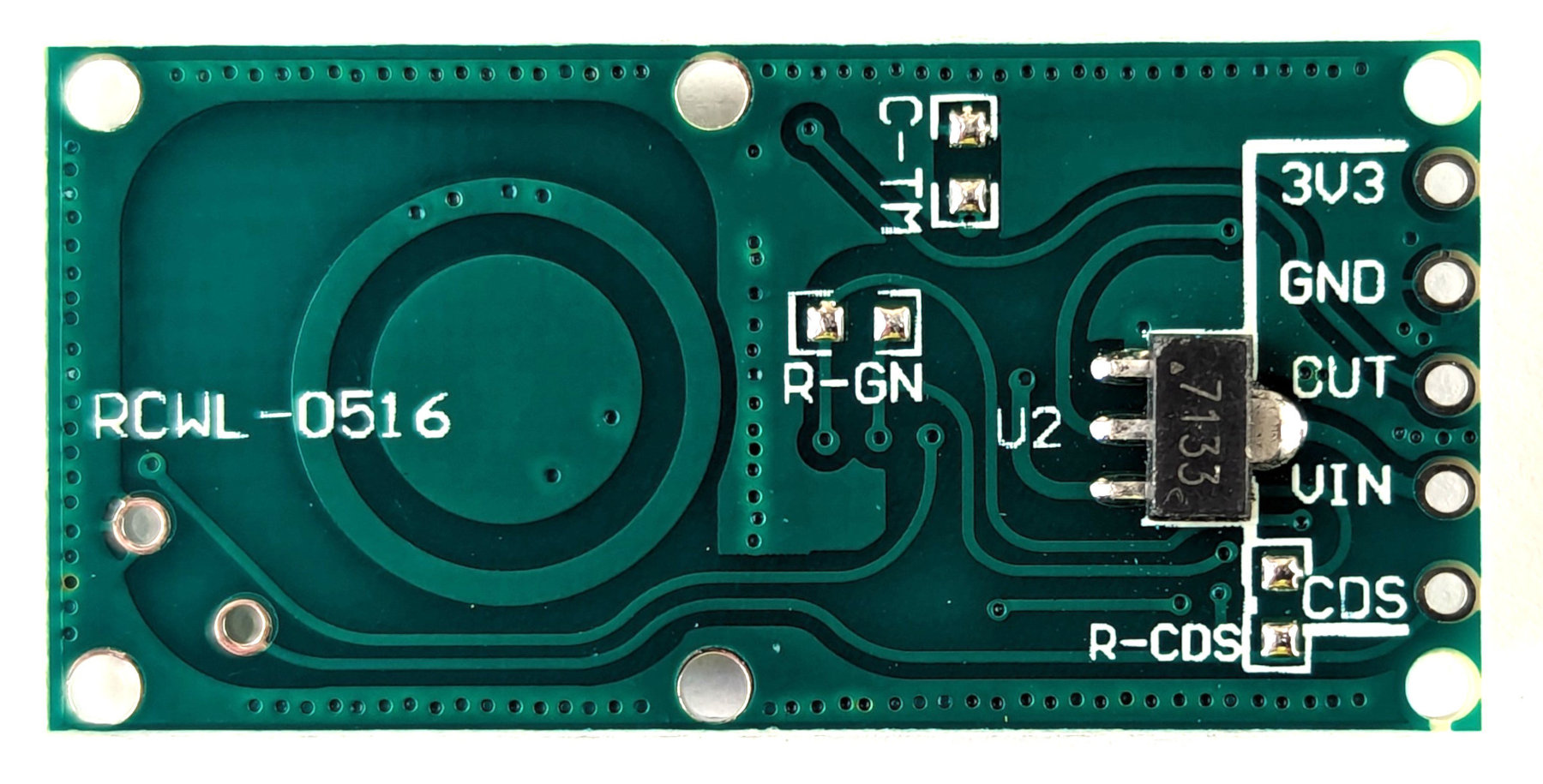
On the rear of the board there are three places that are set aside and labelled to accept components. Be aware that all three will require soldering surface mount devices which will take some considerable care if you haven’t tried it before.
C-TM - This is a space for a capacitor that adjust the time that the device will stay triggered for once it is set. By default is 2 seconds. A description of values that can be used to extend the time is available from Instructables.
R-GN - This component change will adjust the detection range. The default is 7m. If we add a 1M resistor here it will reduce to 5m.
R-RDS - Adding a resistor here will will decrease the effective resistance in series with Light Dependant Resistor (assuming we have it fitted) which lowers the threshold for it to disable the device when it gets brighter. The TLDR explanation (pun intended) is that (assuming you have a LDR fitted in the CDS position) if you put a resister here, the LDR will disable the device at a lower light level.
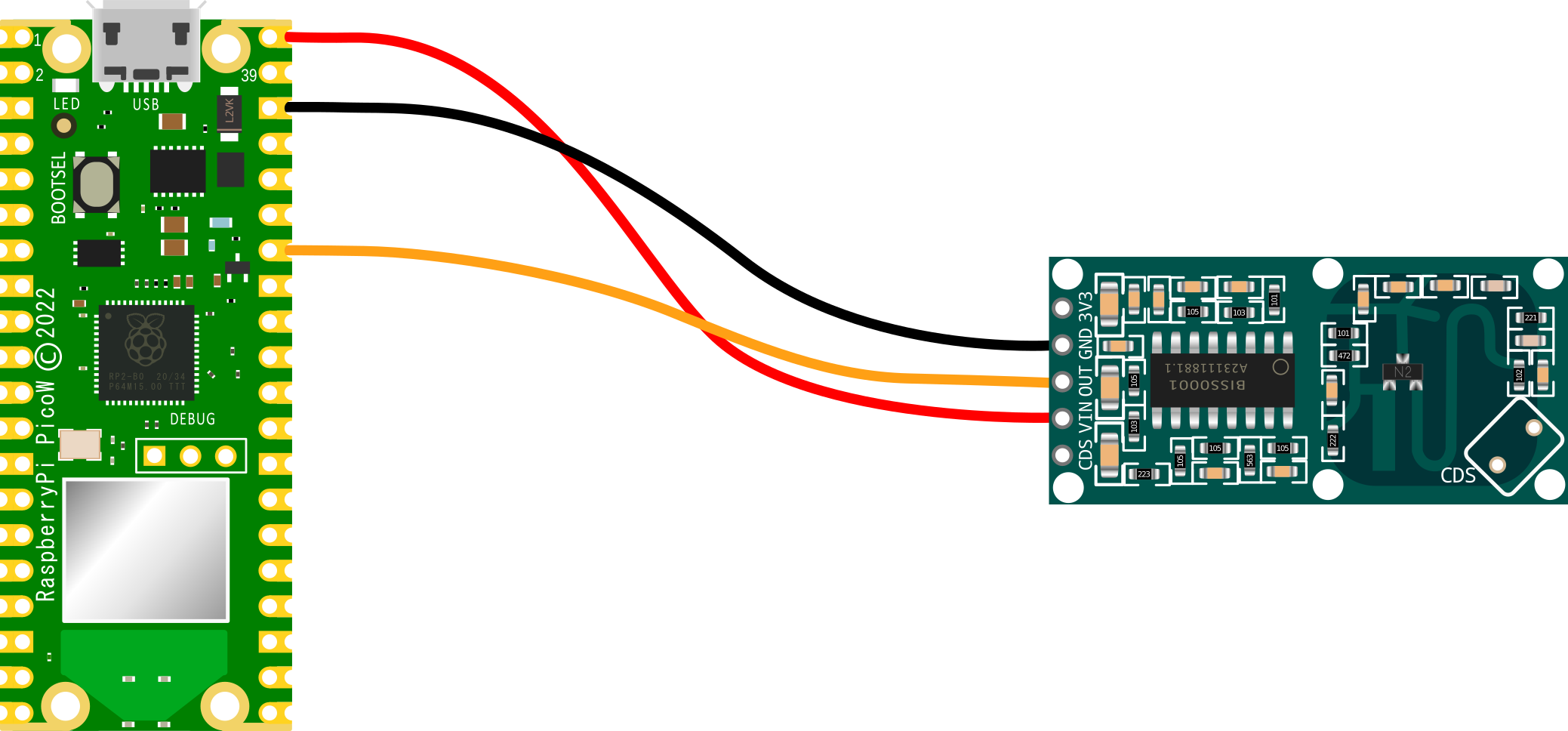
Our connections can be kept pretty simple. We are going to connect power to the sensor and a signal connection that will indicate when it has been triggered.
RWCL-0516 VIN to VBUS (pin 40) on the Pico (Red)
RWCL-0516 GND to GND (pin 38) on the Pico (Black)
RWCL-0516 OUT to GP28 (pin 34) on the Pico (Orange)
Pico connected to RWCL-0516
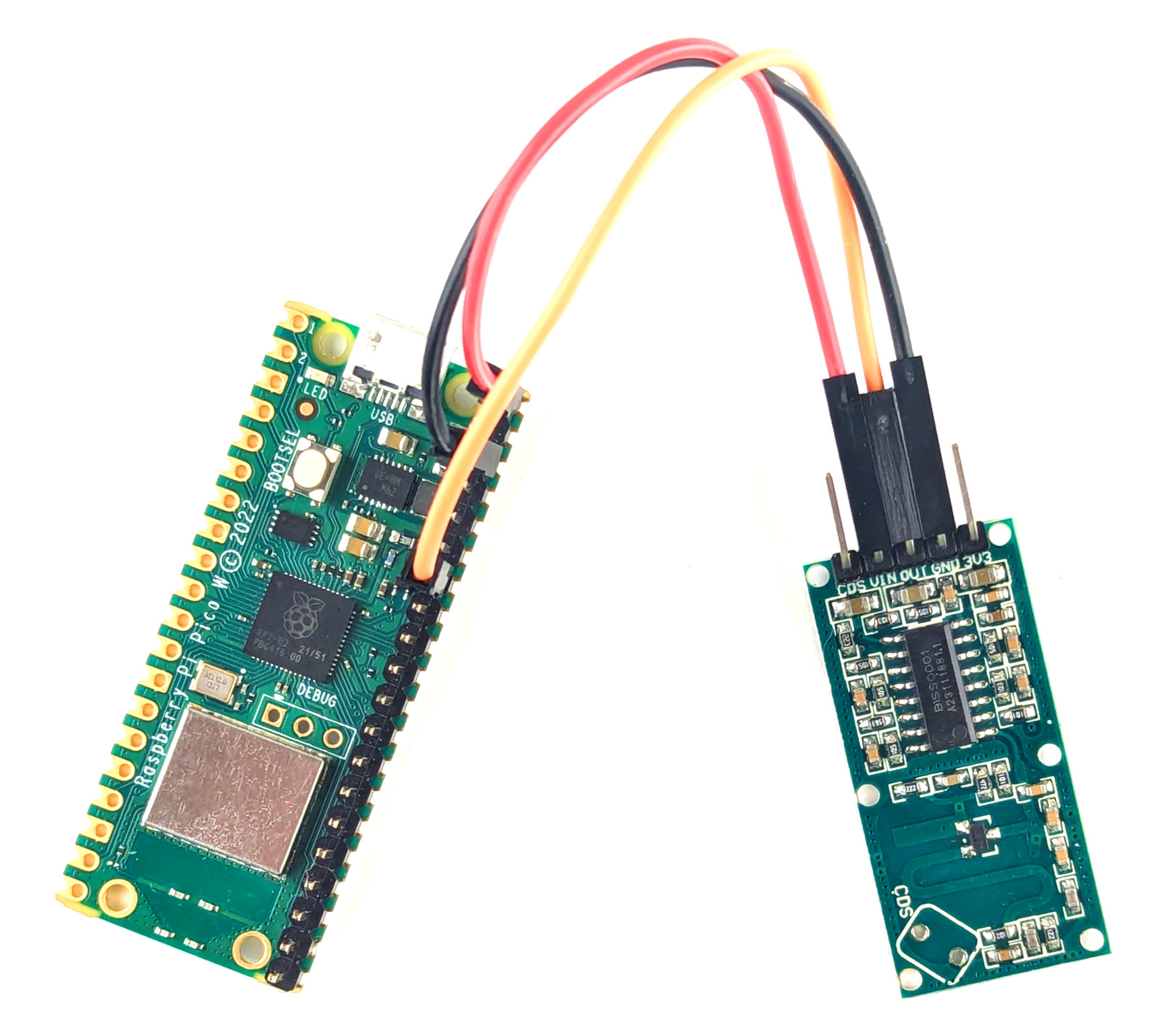
Of course we can simply use our favourite dupont connectors to do the job in the real world.
Pico connected to RWCL-0516 for reals
Code
The code below designates GP28 as the pin that the sensor’s out pin is connected to.
It defines a small function to blink the on-board LED and then two functions to operate if the sensor sees motion (it’s blinking time and printing out a notification) or if the environment around it is still.
importtimeimportmachinemotion=machine.Pin(28,machine.Pin.IN)# Define blinking function for onboard LED defblink_onboard_led(num_blinks):led=machine.Pin('LED',machine.Pin.OUT)foriinrange(num_blinks):led.on()time.sleep(.2)led.off()time.sleep(.2)# What to do if motion detecteddefmoving():print("Motion detected")blink_onboard_led(1)# What to do once motion ceaseddefstill():print("Everything is still")whileTrue:ifmotion.value():moving()else:still()time.sleep(1)
It really is a remarkably simple piece of code that we could add to as we wished to carry out other functions if it senses motion.
Logging to help with troubleshooting. Raspberry Pi Pico and Micropython centric
Alrighty… Let’s get the obvious part of the discussion on this topic out of the way…
There are a wide range of possible mechanisms for troubleshooting depending on the skill level of the practitioner, the complexity of the code and the capabilities of the platform. In short, you will ultimately fall to using the techniques that work for you the best depending on your circumstances.
I am capturing the description of this method, not because I think it is the best or even if I think that it’s advisable. It suited me for a task and so I believed that it might suit me again at some time in the future. Therefore I thought I should write this down so that I don’t forget what the code does, and what better place to write it down than in a book :-).
This particular piece of code is written to capture notes as our Micropython code executes and to write those notes into a log file so that we can examine them at a later date. The particular occasion I needed something like this was when I had a Pico that would run for many days and would then fail. I couldn’t determine why it was failing, and so I decided that a piece of code that would write lines to a file so that I could see when and where the failure occurred would be a good start.
Therefore, the way this piece of code would be used is if we place the initial set-up and function definition at the start of the program we are troubleshooting and then we place the small note capturing code at various places where we want to know that the program has gotten to or looking at values that we want to check.
It captures the time that the event is written, the size of the log file and the message that we want to pass to it. This message can be text and / or values.
Enough talk, this is what it looks like;
importosfrommachineimportRTCrtc=RTC()rtc.datetime()#Check to see if file present and create if necessarytry:os.stat('/log.dat')print("File Exists")except:print("File Missing")f=open("log.dat","w")f.close()deflog(loginfo:str):# Format the timestamptimestamp=rtc.datetime()timestring="%04d-%02d-%02d%02d:%02d:%02d"%(timestamp[0:3]+timestamp[4:7])# Check the file sizefilestats=os.stat('/log.dat')filesize=filestats[6]if(filesize<200000):try:log=timestring+" "+str(filesize)+" "+loginfo+"\n"print(log)withopen("log.dat","at")asf:f.write(log)except:print("Problem saving file")# sample usageval=456text="some information"combo=text+" "+str(val)log(combo)
To make life easier for future me (and hopefully you) here’s the description of some of the parts.
This is so that we can us the os module to determine the size of the file we are generating and to make sure that we don’t write so large a file that it overwhelms our available storage.
RTC is used to generate a timestamp so that we know when an event occurs. Of course, if we don’t set the time initially, we are going to be left with a time stamp that starts at 2021-01-01 00:00:00. We could connect to NTP time first if we had a network connection, but that’s not always going to be available. This way we will at least have a feel for how our comments are being captured relative to each other and the time that the program started. There are several different time modules that we could use to do this. time, utime, and possibly others. Each has some slight differences in terms of the start of the timestamp or similar, and I fell on RTC. It does the job.
If the file that we’re going to use for capturing our information doesn’t exist, we need to create it.
The first use of the open command to append information to a file will create the file if it doesn’t exist, but we will want to check the size of the file before we write anything to it, so this small piece of code checks for its existence and if it isn’t there creates it.
Then we get into the function definition.
We find the time and format it as a string in a nice tidy format. For those of you who are writing your dates in a dd/mm/yyyy format, using the alternative of yyyy/mm/dd makes it easier to sort.
    # Format the timestamp
    timestamp=rtc.datetime()
    timestring="%04d-%02d-%02d %02d:%02d:%02d"%(timestamp[0:3] +
                                                timestamp[4:7])
The os.stat call responds with a range of different metrics (not all of which are applicable for every platform). The one we want is accessed as [6] in the array.
After checking to make sure that our file hasn’t grown too large we combine the time, the size of the file and the information that we want to note specifically (this comes from then individual calls to the function in the program).
We also add a newline "\n" in to break the lines up.
The final block of the code is the piece that we would put in a range of places in our program to capture information.
# sample usage
val = 456
text = "some information"
combo = text + " " + str(val)
log(combo)
This is obviously just a sample, but we have a value val that could be any number used in the program and a comment some information that again could be something that acts as a reference for that portion of the code that we’re wanting to know something about. For example, it could be when the program starts and then when the device connects to the network, and then if it strikes an error in reading a value from a sensor.