
Since this post is a snapshot in time. I recommend that you download a copy of the book which is updated frequently to improve and expand the content.
---------------------------------------
This is the first of three posts working through a project looking at Measuring Recording and Exploring temperature measurements with the Raspberry Pi.
Multiple Temperature Measurements
This project will measure the temperature at multiple points using DS18B20 sensors. This project will use the waterproof version of the sensors since they have more potential practical applications.
This project is a logical follow on to the Single Temperature Measurement project. The differences being the use of multiple sensors and with a slightly more sophisticated approach to recording and exploring our data. It is still a relatively simple hardware set-up.
Measure
Hardware required
- DS18B20 sensors (the waterproof version)
- 10k Ohm resister
- Jumper cables
- Solder
- Heatshrink
Connect
The DS18B20 sensors needs to be connected with the black wires to ground, the red wires to the 3V3 pin and the blue or yellow (some sensors have blue and some have yellow) wires to the GPIO4 pin. A resistor between the value of 4.7k Ohms to 10k Ohms needs to be connected between the 3V3 and GPIO4 pins to act as a ‘pull-up’ resistor.
The Raspbian Operating System image that we are using only supports GPIO4 as a 1-Wire pin, so we need to ensure that this is the pin that we use for connecting our temperature sensor.
The following diagram is a simplified view of the connection.
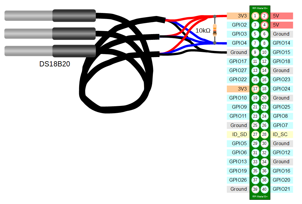
Single DS18B20 Connection
To connect the sensor practically can be achieved in a number of ways. You could use a Pi Cobbler break out connector mounted on a bread board connected to the GPIO pins. But because the connection is relatively simple we could build a minimal configuration that will plug directly onto the appropriate GPIO pins. The resister is concealed under the heatshrink and indicated with the arrow.
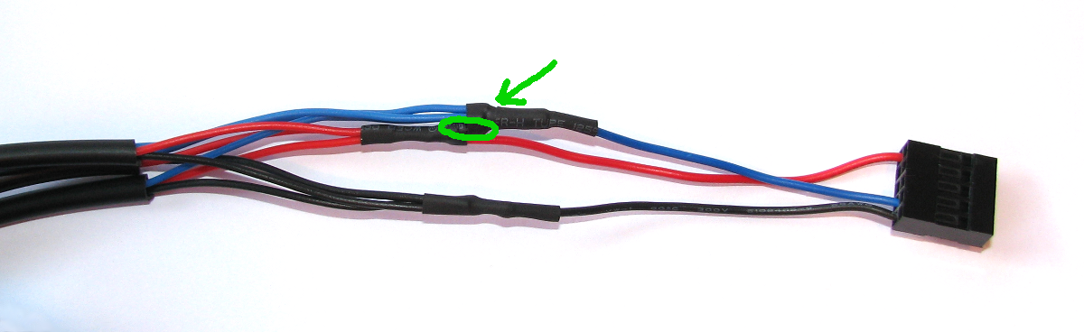
Minimal Single DS18B20 Connection
This version uses a recovered header connector from a computers internal USB cable.
Test
From the terminal as the ‘pi’ user run the command;
modprobe w1-gpio registers the new sensor connected to GPIO4 so that now the Raspberry Pi knows that there is a 1-Wire device connected to the GPIO connector (For more information on the modprobe command check out the Glossary). | modprobe is a Linux program used to add a loadable kernel module (LKM) to the Linux kernel or to remove a LKM from the kernel. It is commonly used to load drivers for automatically detected hardware. |
Then run the command;
modprobe w1-therm tells the Raspberry Pi to add the ability to measure temperature on the 1-Wire system.
To allow the
w1_gpio and w1_therm modules to load automatically at boot we can edit the the /etc/modules file and include both modules there where they will be started when the Pi boots up. To do this edit the /etc/modules file;
Add in the
w1_gpio and w1_therm modules so that the file looks like the following;# /etc/modules: kernel modules to load at boot time.
#
# This file contains the names of kernel modules that should be loaded
# at boot time, one per line. Lines beginning with "#" are ignored.
# Parameters can be specified after the module name.
snd-bcm2835
w1-gpio
w1-therm
Save the file.
Then we change into the
/sys/bus/w1/devices directory and list the contents using the following commands;
(For more information on the
cd command check out the Glossary here. Or to find out more about the ls command go here)
This should list out the contents of the
/sys/bus/w1/devices which should include a number of directories starting 28-. The number of directories should match the number of connected sensors. The portion of the name following the 28- is the unique serial number of each of the sensors.
We then change into one of those directories;
We are then going to view the ‘w1_slave’ file with the
cat command using; |
The output should look something like the following;
73 01 4b 46 7f ff 0d 10 41 : crc=41 YES
73 01 4b 46 7f ff 0d 10 41 t=23187
At the end of the first line we see a
YES for a successful CRC check (CRC stands forCyclic Redundancy Check, a good sign that things are going well). If we get a response like NO or FALSE or ERROR, it will be an indication that there is some kind of problem that needs addressing. Check the circuit connections and start troubleshooting.
At the end of the second line we can now find the current temperature. The
t=23187 is an indication that the temperature is 23.187 degrees Celsius (we need to divide the reported value by 1000). |
To convert from degrees Celsius to degrees Fahrenheit, multiply by 9, then divide by 5, then add 32.
|
cd into each of the 28-xxxx directories in turn and run the cat w1_slave command to check that each is operating correctly. It may be useful at this stage to label the individual sensors with their unique serial numbers to make it easy to identify them correctly later.The post above (and heaps of other stuff) is in the book 'Raspberry Pi: Measure, Record, Explore' that can be downloaded for free (or donate if you really want to :-)).
No comments:
Post a Comment