Raspberry Pi Pico Tips and Tricks

Sunday 30 December 2018

Raspberry Pi setup as a bridged WiFi access point


Per instructions at raspberrypi.org with some modification to make it easier to follow and for localisation.
Install the most recent raspbian disk image onto a microSD card using Disk Imager or similar.
Create a new file on the microSD card called ssh. I simply right click on the folder and go 'Create new text document'. The file will have the suffix .txt, but this won't matter. This allows ssh to be enabled on first boot.
Unmount the microSD card and put it into the Pi. Have the Pi connected to a monitor so that you can see what the IP address is when it finishes booting. Alternatively, check the connected devices on a router page.
Turn the power on. The automatic re-sizing will be carried out and the IP address will be shown.
Start WinSCP. Use the IP address, port 22, the username pi and the password raspberry to connect. You will be warned about a potential security breach because the host key won't match the one that WinSCP has in its cache. This is fine. Just press the 'Update' button to continue.
sudo apt-get update sudo apt-get upgrade
To use the Raspberry Pi as an bridged access point is to provide wireless connections to a wired Ethernet connection, so that anyone logged into the access point can access the internet, providing of course that the wired Ethernet on the Pi can connect to the internet via some sort of router.
To do this, a 'bridge' needs to put in place between the wireless device and the Ethernet device on the access point Raspberry Pi. This bridge will pass all traffic between the two interfaces. Install the following packages to enable the access point setup and bridging.
sudo apt-get install hostapd bridge-utils
Since the configuration files are not ready yet, turn the new software off as follows:
sudo systemctl stop hostapd
Bridging creates a higher-level construct over the two ports being bridged. It is the bridge that is the network device, so we need to stop the eth0 and wlan0 ports being allocated IP addresses by the DHCP client on the Raspberry Pi.
sudo nano /etc/dhcpcd.conf
Add denyinterfaces wlan0 and denyinterfaces eth0 to the end of the file (but above any other added interface lines) and save the file.
Add a new bridge, which in this case is called br0.
sudo brctl addbr br0
Connect the network ports. In this case, connect eth0 to the bridge br0.
sudo brctl addif br0 eth0
Now the interfaces file needs to be edited to adjust the various devices to work with bridging.
sudo nano /etc/network/interfaces
Make the following edits by adding the bridging information at the end of the file.
# Bridge setup
auto br0
iface br0 inet manual
bridge_ports eth0 wlan0 
You need to edit the hostapd configuration file, located at /etc/hostapd/hostapd.conf, to add the various parameters for your wireless network. After initial install, this will be a new/empty file.
sudo nano /etc/hostapd/hostapd.conf
Add the following

interface=wlan0
bridge=br0
#driver=nl80211
ssid=water_tank
hw_mode=g
channel=11
wmm_enabled=0
macaddr_acl=0
auth_algs=1
ignore_broadcast_ssid=0
wpa=2
wpa_passphrase=water_tank_password
wpa_key_mgmt=WPA-PSK
wpa_pairwise=TKIP
rsn_pairwise=CCMP
We now need to tell the system where to find this configuration file.
sudo nano /etc/default/hostapd
Find the line with #DAEMON_CONF, and replace it with this:
DAEMON_CONF="/etc/hostapd/hostapd.conf"
Now reboot the Raspberry Pi.
sudo reboot
There should now be a functioning bridge between the wireless LAN and the Ethernet connection on the Raspberry Pi, and any device associated with the Raspberry Pi access point will act as if it is connected to the access point's wired Ethernet.
The ifconfig command will show the bridge, which will have been allocated an IP address via the wired Ethernet's DHCP server. The wlan0 and eth0 no longer have IP addresses, as they are now controlled by the bridge. It is possible to use a static IP address for the bridge if required, but generally, if the Raspberry Pi access point is connected to a ADSL router, the DHCP address will be fine.

Tuesday 24 April 2018

Multiple Temperature Measurements with the DS18B20 on the Raspberry Pi

This post is part of the book Raspberry Pi Computing: Temperature Measurement which can be downloaded from Leanpub for free (or donate if you wish).

Multiple Temperature Measurements

This project will measure the temperature at multiple points using DS18B20 sensors. We will use the waterproof version of the sensors since they are more practical for external applications.

The DS18B20 Sensor

The DS18B20 is a ‘1-Wire’ digital temperature sensor manufactured by Maxim Integrated Products Inc. It provides a 9-bit to 12-bit precision, Celsius temperature measurement and incorporates an alarm function with user-programmable upper and lower trigger points.
Its temperature range is between -55C to 125C and they are accurate to +/- 0.5C between -10C and +85C.
It is called a ‘1-Wire’ device as it can operate over a single wire bus thanks to each sensor having a unique 64-bit serial code that can identify each device.
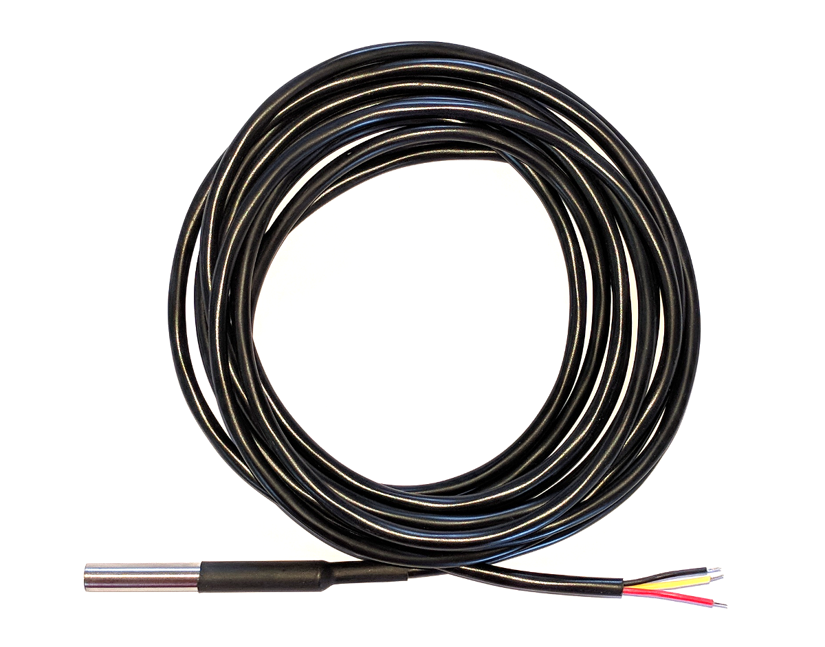
While the DS18B20 comes in a TO-92 package, it is also available in a waterproof, stainless steel package that is pre-wired and therefore slightly easier to use in conditions that require a degree of protection. The measurement project that we will undertake will use the waterproof version.

Single DS18B20 Sensor

The sensors can come with a couple of different wire colour combinations. They will typically have a black wire that needs to be connected to ground. A red wire that should be connected to a voltage source (in our case a 3.3V pin from the Pi) and a blue or yellow wire that carries the signal.
The DS18B20 can be powered from the signal line, but in our project we will use an external voltage supply (from the Pi).

Measure

Hardware required

  • 3 x DS18B20 sensors (the waterproof version)
  • 10k Ohm resister
  • Jumper cables with Dupont connectors on the end
  • Solder
  • Heat-shrink

Connect

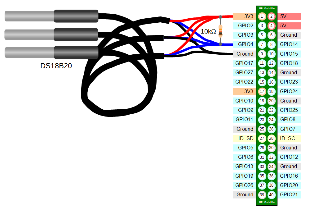
The DS18B20 sensors needs to be connected with the black wires to ground, the red wires to the 3V3 pin and the blue or yellow (some sensors have blue and some have yellow) wires to the GPIO4 pin. A resistor between the value of 4.7k Ohms to 10k Ohms needs to be connected between the 3V3 and GPIO4 pins to act as a ‘pull-up’ resistor.
The Raspbian Operating System image that we are using only supports GPIO4 as a 1-Wire pin, so we need to ensure that this is the pin that we use for connecting our temperature sensor.
The following diagram is a simplified view of the connection.

Triple DS18B20 Connection

Connecting the sensor practically can be achieved in a number of ways. You could use a Pi Cobbler break out connector mounted on a bread board connected to the GPIO pins. But because the connection is relatively simple we could build a minimal configuration that will plug directly onto the appropriate GPIO pins using Dupont connectors. The resister is concealed under the heat-shrink and indicated with the arrow.

Minimal Triple DS18B20 Connection

This version uses a recovered header connector from a computers internal USB cable.

Enable

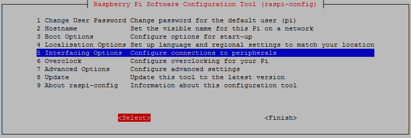
We’re going to go back to the Raspberry Pi Software Configuration Tool as we need to enable the 1-wire option. This can be done by running the following command;


Select ‘Interfacing options`;

Interfacing Options
Interfacing Options

Then select the 1-wire option and enable it.

1-wire enabling
1-wire enabling

When you back out of the menu you will be asked to reboot the device. Do this and then log in again.


Test

From the terminal as the ‘pi’ user run the command;


modprobe w1-gpio registers the new sensors connected to GPIO4 so that now the Raspberry Pi knows that there is a 1-Wire device connected to the GPIO connector (For more information on the modprobe command check out the details here).


Then run the command;


modprobe w1-therm tells the Raspberry Pi to add the ability to measure temperature on the 1-Wire system.
To allow the w1_gpio and w1_therm modules to load automatically at boot we can edit the the /etc/modules file and include both modules there where they will be started when the Pi boots up. To do this edit the /etc/modules file;


Add in the w1_gpio and w1_therm modules so that the file looks like the following;

# /etc/modules: kernel modules to load at boot time.
#
# This file contains the names of kernel modules that should be loaded
# at boot time, one per line. Lines beginning with "#" are ignored.

w1-gpio
w1-therm

Save the file.
Then we change into the /sys/bus/w1/devices directory and list the contents using the following commands;


(For more information on the cd command check out the reference here. Or to find out more about the ls command go here)
This should list out the contents of the /sys/bus/w1/devices which should include a number of directories starting 28-. The number of directories should match the number of connected sensors. The portion of the name following the 28- is the unique serial number of each of the sensors.
We then change into one of those directories;


We are then going to view the ‘w1_slave’ file with the cat command using;


The output should look something like the following;

73 01 4b 46 7f ff 0d 10 41 : crc=41 YES
73 01 4b 46 7f ff 0d 10 41 t=23187

At the end of the first line we see a YES for a successful CRC check (CRC stands for Cyclic Redundancy Check, a good sign that things are going well). If we get a response like NO or FALSE or ERROR, it will be an indication that there is some kind of problem that needs addressing. Check the circuit connections and start troubleshooting.
At the end of the second line we can now find the current temperature. The t=23187 is an indication that the temperature is 23.187 degrees Celsius (we need to divide the reported value by 1000).


cd into each of the 28-xxxx directories in turn and run the cat w1_slave command to check that each is operating correctly. It may be useful at this stage to label the individual sensors with their unique serial numbers to make it easy to identify them correctly later
For more info on using the Raspberry Pi or for a range of other free to download books (there are no catches) check out the list here.

Ultrasonic Distance Measurement with a Raspberry Pi

This post is part of the book Raspberry Pi Computing: Ultrasonic Distance Measurement which can be downloaded from Leanpub for free (or donate if you wish).

Ultrasonic Distance Measurement

This project will measure distance using an ultrasonic sensor module. We will use the JSN-SR04T sensor since it utilises a single waterproof send/receive audio module that will be useful for my particular application, but an alternative sensor called the HC-SR04 is a drop in replacement that combines the electronic and audio modules. It also breaks out the send and receive components which allows for measuring closer distances down to 2cm.

The JSN-SR04T Sensor

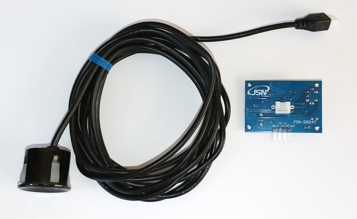
The JSN-SR04T is an ultrasonic ranging sensor that comprises an electronics module and a waterproof audio module connected by a long cable. It is designed to measure distance by sending out a high frequency pattern of pulses when triggered and to return a signal that corresponds to the length of time that it has taken for the pulses to travel out and be reflected back to the audio module.

Electronics and Audio modules for JSN-SR04T

JSN-SR04T Specifications

Specifications:
  • Operating voltage: DC 5V
  • Quiescent current: 5mA
  • Total current work: 30mA
  • Acoustic emission frequency: 40khz
  • Farthest distance: 4.5m
  • Shortest distance: 25cm
  • Module size: 41mm x 28.5mm
  • Resolution: about 0.5cm
  • Angle: less than 50 degrees
  • Working temperature: -10 to 70°C
Wiring:
  • +5V (Power supply)
  • Trig (Receives the trigger to operate)
  • Echo (Signals time taken for audio send/receive trip)
  • GND (Ground)


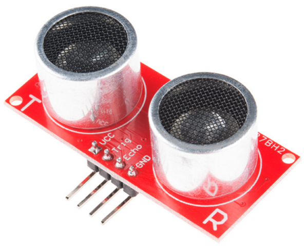
The device is touted as a drop-in replacement for the HC-SR04 which combines the electronics and audio modules and which separates the transmit and receive sensors.

HC-SR04. Image Courtesy sparkfun.com

Measure

Hardware required

  • 1 x JSN-SR04T sensor
  • 1k Ohm resister
  • 2k Ohm resister
  • Jumper cables with Dupont connectors on the end
  • Solder
  • Heat-shrink

Connect

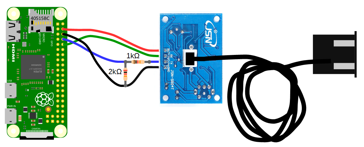
For the sake of keeping the connecting pins together on the Pi’s GPIO block we will be connecting pins 4,6,8 and 10 to the JSN-SR04T electronics module. The following diagram provides a high level overview of the complete chain.

Electronics and Audio modules for JSN-SR04T

  • Pin 4 connects directly to the +5V connector
  • Pin 6 Connects directly to the GND connector, but is incorporated into the voltage divider for the Echo pin.
  • Pin 8 connects to the centre of the voltage divider
  • Pin 10 connects directly to the Trig connector.
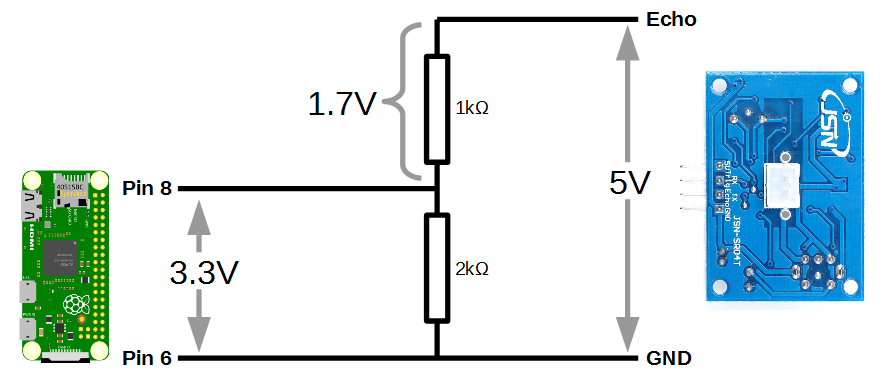
As we noted earlier, the Raspberry Pi provides general purpose digital input/output pins (called GPIO pins) that you can use for reading digital logic signals. In our case, we will want to apply the output signal from the ‘Echo’ pin to them. Unfortunately the output voltage from the Echo pin is 5V and the GPIO pins on the Raspberry Pi are only able to operate safely at voltage levels of 3.3V.
To safely apply the correct voltage to the Pi we can employ a voltage divider which divides the signal in a ratio corresponding to the resistance of two connected resistors. In the following diagram we can see that when a 5V signal is applied from the JSN-SR04T, 1.7V is dropped across the 1k Ohm resistor and 3.3V is across the 2k Ohm resistor.

How the voltage divider works

Basic Operation

A pulse of at least 10us is applied to the trigger (Trig) pin of the electronics module.

A trigger signal starts the process

This will automatically generate 8 audio pulses at 40kHz from the audio transmitter / receiver module.

This generates 8, 40kHz pulses

The 8 pulses will reflect off a surface and be received back at the audio module.

The 8 pulses are reflected back to the audio module

The electronics module will generate a signal from the Echo pin that corresponds to the time between the audio pulses being transmitted and the reflections being received. If no reflected audio is received, a signal of time, t = 38ms will be generated.

The signal from the Echo pin corresponds to the time

The distance from the audio module to the reflecting surface can be found by multiplying the time that the echo pin was high (represented as 12ms in the diagram)by the speed of sound (340m/s) and dividing by 2 (since the sound travelled out and back). Therefore;

calculating the distance

Our object is 2.04 metres away!

Test

The following python program can be saved onto our Pi as distance.py and run from the command line using;

#!/usr/bin/python
#encoding:utf-8

import RPi.GPIO as GPIO                    #Import GPIO library
import time                                #Import time library
GPIO.setmode(GPIO.BCM)                     #Set GPIO pin numbering 

TRIG = 15                                  #Associate pin 15 to TRIG
ECHO = 14                                  #Associate pin 14 to Echo

print "Distance measurement in progress"

GPIO.setup(TRIG,GPIO.OUT)                  #Set pin as GPIO out
GPIO.setup(ECHO,GPIO.IN)                   #Set pin as GPIO in

while True:

  GPIO.output(TRIG, False)                 #Set TRIG as LOW
  print "Waiting For Sensor To Settle"
  time.sleep(2)                            #Delay of 2 seconds

  GPIO.output(TRIG, True)                  #Set TRIG as HIGH
  time.sleep(0.00001)                      #Delay of 0.00001 seconds
  GPIO.output(TRIG, False)                 #Set TRIG as LOW

  while GPIO.input(ECHO)==0:               #Check if Echo is LOW
    pulse_start = time.time()              #Time of the last  LOW pulse

  while GPIO.input(ECHO)==1:               #Check whether Echo is HIGH
    pulse_end = time.time()                #Time of the last HIGH pulse 

  pulse_duration = pulse_end - pulse_start #pulse duration to a variable

  distance = pulse_duration * 17150        #Calculate distance
  distance = round(distance, 2)            #Round to two decimal points

  if distance > 20 and distance < 400:     #Is distance within range
    print "Distance:",distance - 0.5,"cm"  #Distance with calibration
  else:
    print "Out Of Range"                   #display out of range

This program is available as distance.py with the code samples that can be downloaded with the book from Leanpub.
When executed the sensor will settle and then start displaying the distance every two seconds.

Waitng For Sensor To Settle
Distance: 53.44 cm
Waitng For Sensor To Settle
Distance: 52.95 cm

Move the audio module about and confirm that it is operating as expected.
For more info on using the Raspberry Pi or for a range of other free to download books (there are no catches) check out the list here.