
Multiple Temperature Measurements
This project will measure the temperature at multiple points using DS18B20 sensors. We will use the waterproof version of the sensors since they are more practical for external applications.
The DS18B20 Sensor
The DS18B20 is a ‘1-Wire’ digital temperature sensor manufactured by Maxim Integrated Products Inc. It provides a 9-bit to 12-bit precision, Celsius temperature measurement and incorporates an alarm function with user-programmable upper and lower trigger points.
Its temperature range is between -55C to 125C and they are accurate to +/- 0.5C between -10C and +85C.
It is called a ‘1-Wire’ device as it can operate over a single wire bus thanks to each sensor having a unique 64-bit serial code that can identify each device.
While the DS18B20 comes in a TO-92 package, it is also available in a waterproof, stainless steel package that is pre-wired and therefore slightly easier to use in conditions that require a degree of protection. The measurement project that we will undertake will use the waterproof version.
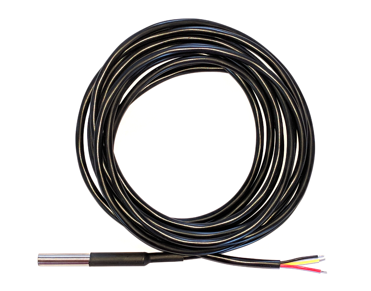
The sensors can come with a couple of different wire colour combinations. They will typically have a black wire that needs to be connected to ground. A red wire that should be connected to a voltage source (in our case a 3.3V pin from the Pi) and a blue or yellow wire that carries the signal.
The DS18B20 can be powered from the signal line, but in our project we will use an external voltage supply (from the Pi).
Measure
Hardware required
- 3 x DS18B20 sensors (the waterproof version)
- 10k Ohm resister
- Jumper cables with Dupont connectors on the end
- Solder
- Heat-shrink
Connect
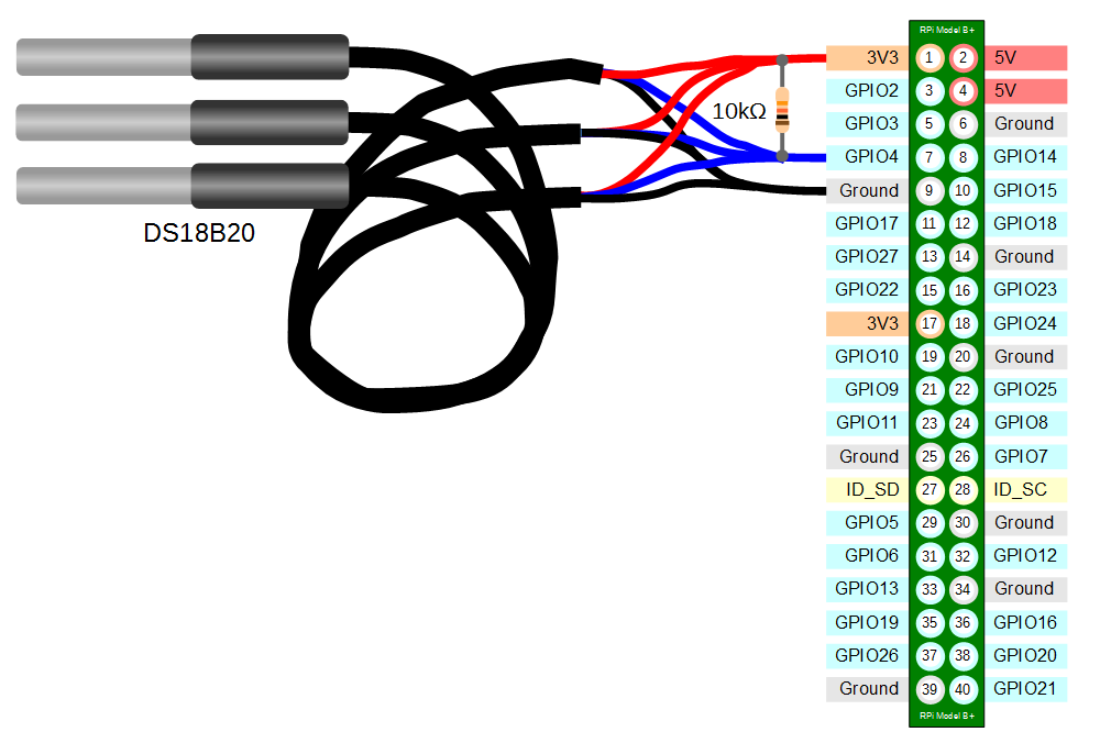
The DS18B20 sensors needs to be connected with the black wires to ground, the red wires to the 3V3 pin and the blue or yellow (some sensors have blue and some have yellow) wires to the GPIO4 pin. A resistor between the value of 4.7k Ohms to 10k Ohms needs to be connected between the 3V3 and GPIO4 pins to act as a ‘pull-up’ resistor.
The Raspbian Operating System image that we are using only supports GPIO4 as a 1-Wire pin, so we need to ensure that this is the pin that we use for connecting our temperature sensor.
The following diagram is a simplified view of the connection.
Connecting the sensor practically can be achieved in a number of ways. You could use a Pi Cobbler break out connector mounted on a bread board connected to the GPIO pins. But because the connection is relatively simple we could build a minimal configuration that will plug directly onto the appropriate GPIO pins using Dupont connectors. The resister is concealed under the heat-shrink and indicated with the arrow.
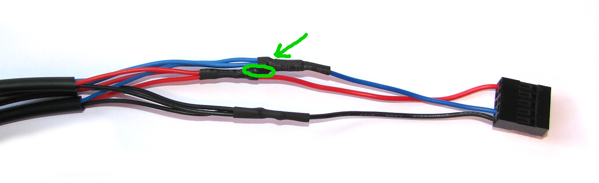
This version uses a recovered header connector from a computers internal USB cable.
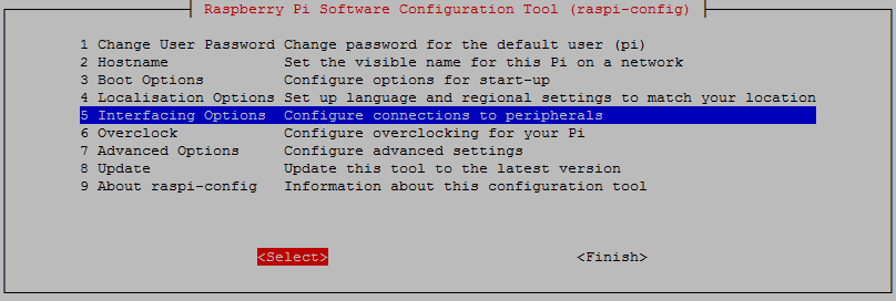
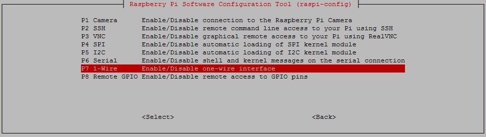
Enable
We’re going to go back to the Raspberry Pi Software Configuration Tool as we need to enable the 1-wire option. This can be done by running the following command;
Select ‘Interfacing options`;
Then select the 1-wire option and enable it.
When you back out of the menu you will be asked to reboot the device. Do this and then log in again.
Test
From the terminal as the ‘pi’ user run the command;
modprobe w1-gpio registers the new sensors connected to GPIO4 so that now the Raspberry Pi knows that there is a 1-Wire device connected to the GPIO connector (For more information on the modprobe command check out the details here).
Then run the command;
modprobe w1-therm tells the Raspberry Pi to add the ability to measure temperature on the 1-Wire system.
To allow the
w1_gpio and w1_therm modules to load automatically at boot we can edit the the /etc/modules file and include both modules there where they will be started when the Pi boots up. To do this edit the /etc/modules file;
Add in the
w1_gpio and w1_therm modules so that the file looks like the following;# /etc/modules: kernel modules to load at boot time.
#
# This file contains the names of kernel modules that should be loaded
# at boot time, one per line. Lines beginning with "#" are ignored.
w1-gpio
w1-therm
Save the file.
Then we change into the
/sys/bus/w1/devices directory and list the contents using the following commands;
(For more information on the
cd command check out the reference here. Or to find out more about the ls command go here)
This should list out the contents of the
/sys/bus/w1/devices which should include a number of directories starting 28-. The number of directories should match the number of connected sensors. The portion of the name following the 28- is the unique serial number of each of the sensors.
We then change into one of those directories;
We are then going to view the ‘w1_slave’ file with the
cat command using;
The output should look something like the following;
At the end of the first line we see a
YES for a successful CRC check (CRC stands for Cyclic Redundancy Check, a good sign that things are going well). If we get a response like NO or FALSE or ERROR, it will be an indication that there is some kind of problem that needs addressing. Check the circuit connections and start troubleshooting.
At the end of the second line we can now find the current temperature. The
t=23187 is an indication that the temperature is 23.187 degrees Celsius (we need to divide the reported value by 1000).cd into each of the 28-xxxx directories in turn and run the cat w1_slave command to check that each is operating correctly. It may be useful at this stage to label the individual sensors with their unique serial numbers to make it easy to identify them correctly later
Thank you for sharing
ReplyDelete