
The Raspberry Pi Pico includes support to the I2C communications protocol through two I2C controllers which combined service a total of 12 separate connection pair options.
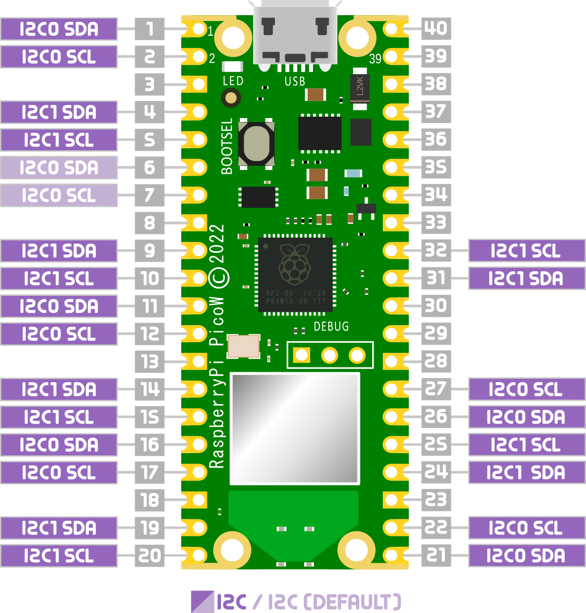
Right from the outset, this does not mean that we can hook up multiple devices (or string of devices) to multiple connection points that use the same controller. One device or string of devices per controller only. That means that we are limited to a total of 127 daisy chained devices per controller. That should be enough for a start :-).
I've written this short explanation as part of the much larger book 'Raspberry Pi Pico Tips and Tricks'. You can download it for free from here.
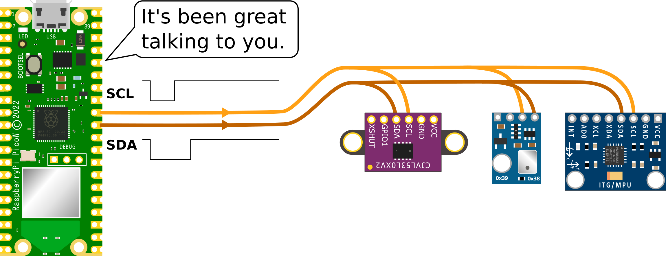
I2C (Inter-Integrated Circuit) is a serial communication protocol that allows devices to communicate with each other over a shared bus. It was developed in the 1980s by Philips Semiconductors as a way to reduce the number of wires needed to connect devices, and has become widely used in a variety of applications.
I2C uses a two-wire interface, consisting of a serial data line (SDA) and a serial clock line (SCL). Devices that use I2C are called ‘slaves’, and they are connected to a ‘master’ device (usually a microcontroller or processor) through these two wires. The master device controls the communication by generating the clock signal and sending/receiving data on the SDA line.
I2C is a very useful protocol because it allows multiple devices to communicate with a single microcontroller or processor using just two wires, making it well suited for use in embedded systems and other applications where space and resources are limited. It is also relatively simple to implement, making it a popular choice for many applications.
How does I2C work?
The master device controls the communication by generating the clock signal and sending/receiving data on the SDA line. The slave devices are connected to the master device through the SDA and SCL lines, and they respond to the commands and requests of the master device.
Here is a brief overview of how I2C works:
- The master device starts the communication by pulling the SDA line low while the SCL line is high and then pulling the SCL line low as well, indicating the start of a new data transfer.

- The master device then sends a 7-bit slave address followed by a read/write bit, indicating whether it wants to read data from or write data to the slave device.

- If the slave device recognizes its own address, it sends an acknowledgement (ACK) by pulling the SDA line low. If the slave device does not recognize its own address, it does not send an ACK and the communication ends.

- If the master device wants to write data to the slave device, it sends the data byte by byte, followed by an ACK from the slave device after each byte. If the master device wants to read data from the slave device, it sends a request for data and the slave device responds by sending a byte of data followed by an ACK from the master device.


- The communication ends when the master device sends a stop condition by pulling the SDA line high while the SCL line is high.
Finding and I2C devices connected to the Raspberry Pi Pico
On the Raspberry Pi Pico, I2C is implemented using a hardware peripheral called the I2C controller, which is part of the Pico’s RP2040 microcontroller. The I2C controller is responsible for generating the clock signal and managing the communication between the Pico and I2C slave devices.
To use I2C on the Raspberry Pi Pico, you will need to import the machine module and use its I2C class.
The following code that demonstrates how to scan for I2C slave devices on the Raspberry Pi Pico and print the addresses of the detected devices.
import machine

# Create an I2C object with the specified SDA and SCL pins
i2c = machine.I2C(sda=machine.Pin(22), scl=machine.Pin(23))

# Scan for slave devices on the I2C bus
devices = i2c.scan()

# Print the addresses of the detected devices
print(devices)
This code creates an I2C object using the SDA and SCL pins 22 and 23, respectively, and uses the scan() method to detect slave devices on the I2C bus. It then prints the addresses of the detected devices.
No comments:
Post a Comment