
Motion Detection using a Microwave Sensor
What is a Doppler Sensor?
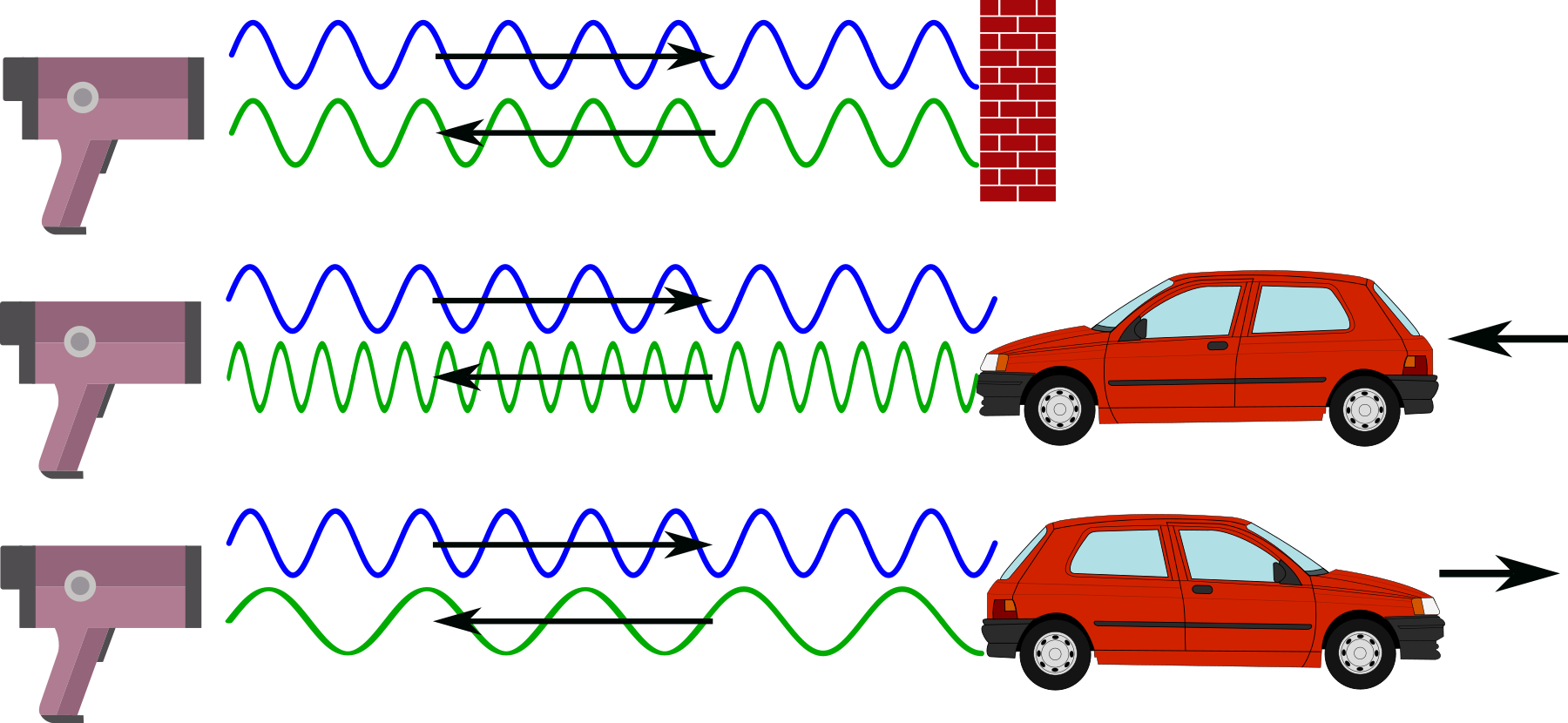
The Doppler Effect
The Doppler effect is named after Christian Doppler who was an Austrian physicist that described the effect in the 1800s. The most common example that most people have experienced is when a car or a train sounding its horn moves towards and then past us. While the car/train is moving towards us the pitch of the horn is high and as it passes us the pitch changes to a lower tone.
Of course some will instantly recognise the effect from the costume worn by Jim Parsons as the character ‘Sheldon Cooper’ in the episode of CBS’s comedy, ‘The Big Bang Theory’ titled ‘The Middle Earth Paradigm’.

This is also the technique used by police forces to determine the speed of motorists on the road. A speed camera or ‘radar gun’ emits a specific Radio Frequency (RF) and since the Doppler effect will make any reflected frequency lower if the car is moving away from the speed camera or higher if the car is moving towards the speed camera, measuring the frequency difference between the emitted signal and the reflected signal can determine the speed of the vehicle.
How does a Microwave Doppler Sensor Work?
A microwave Doppler sensor starts with an electronic device called an ‘oscillator’. This device will set the frequency of operation for the unit and allows the transmitter to broadcast a specific frequency from a built in transmitting / receiving antenna. Once broadcast, the signals reflect off the surroundings and are then returned to the sensor and collected by a receiver on the board. This reflected signal will vary in frequency (according to the Doppler effect) if any of the objects that the signal bounced off were moving towards or away from the transmitter. This received signal is then mixed with the original oscillator frequency. The mixing process will produce a difference frequency that is the difference between the original oscillator and the reflected signals.
So when our sensor sees a difference frequency of significant strength, it knows that there has been something moving close by and can generate a signal to represent it.
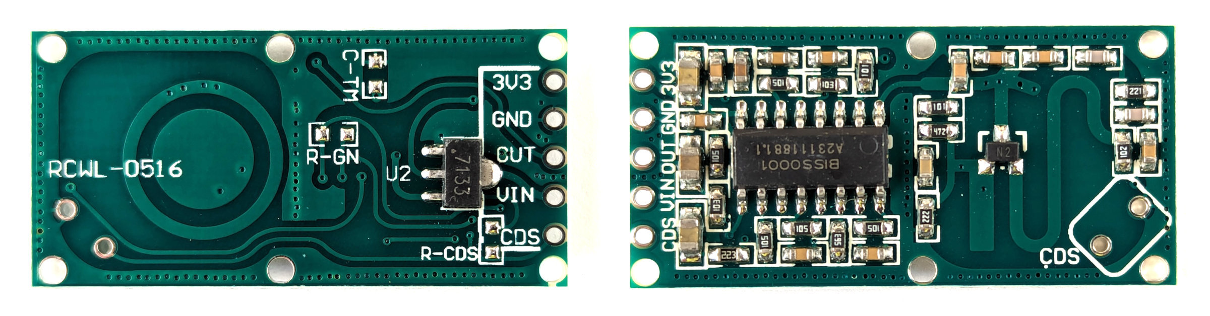
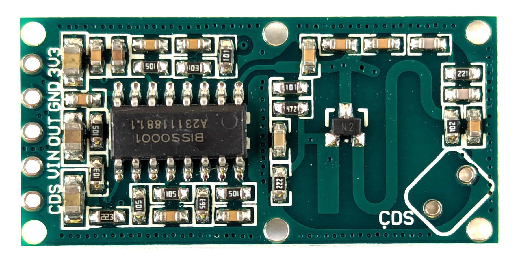
The RWCL-0516 Microwave Radar Sensor
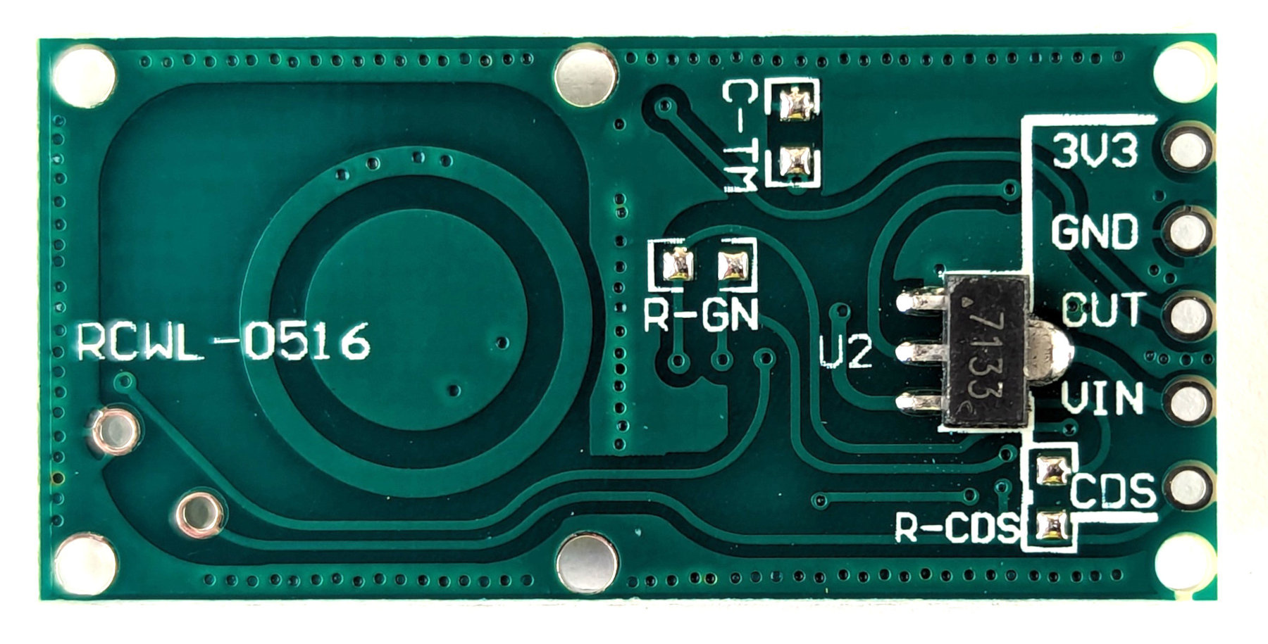
The sensor that we will use is a very simple device that can take an input voltage of between 4 and 28V. With this it will generate a frequency using an oscillator of around 3.182GHz. The oscillator includes an inductor and capacitor that are formed by the copper etched into the board itself. We can see these as the concentric circles on one side and the ‘S’ shape on the other.
The transmitted frequency is not particularly directional, so anything moving around the unit out to a maximum distance of between 5 to 7 meters can be detected. In fact, because the signal is high enough, it will pass through some semi-solid objects (such as a covering container).
Once movement has been detected an output pin is set to ‘high’ for 2 seconds to identify that there has been a trigger.
The RWCL-0516 has five pins as follows
- 3v3 - This is a 3.3v output that can be used for powering other devices (Just to be clear. This is NOT the connection point to power the RWCL-0516).
- GND - The ground reference point
- OUT - This is the output pin that will indicate movement when it occurs.
- VIN - This is where our input voltage is applied (between 4 to 28V).
- CDS - This pin will allow us to disable an optional light sensor on the board (we won’t be fitting this in our example)
The board also has the provision to add components that can adjust the function of the unit.
- On the front side of the board (the side with the majority of the components) there is a space labelled CDS. This is short for ‘Cadmium DiSulphide’. This is the location where a Light Dependant Resister (LDR) can be added to disable the board when there is sufficient light.
On the rear of the board there are three places that are set aside and labelled to accept components. Be aware that all three will require soldering surface mount devices which will take some considerable care if you haven’t tried it before.
- C-TM - This is a space for a capacitor that adjust the time that the device will stay triggered for once it is set. By default is 2 seconds. A description of values that can be used to extend the time is available from Instructables.
- R-GN - This component change will adjust the detection range. The default is 7m. If we add a 1M resistor here it will reduce to 5m.
- R-RDS - Adding a resistor here will will decrease the effective resistance in series with Light Dependant Resistor (assuming we have it fitted) which lowers the threshold for it to disable the device when it gets brighter. The TLDR explanation (pun intended) is that (assuming you have a LDR fitted in the CDS position) if you put a resister here, the LDR will disable the device at a lower light level.
A good deal of information on the unit can be found on the excellent GitHub page maintained by Joe Desbonnet here.
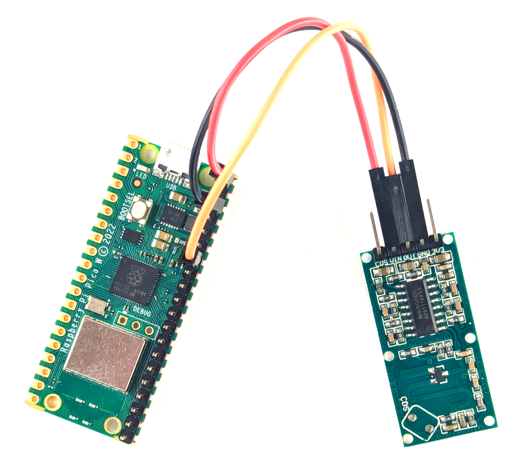
Connecting the RWCL-0516 Sensor Up to the Pico
Our connections can be kept pretty simple. We are going to connect power to the sensor and a signal connection that will indicate when it has been triggered.
- RWCL-0516 VIN to VBUS (pin 40) on the Pico (Red)
- RWCL-0516 GND to GND (pin 38) on the Pico (Black)
- RWCL-0516 OUT to GP28 (pin 34) on the Pico (Orange)
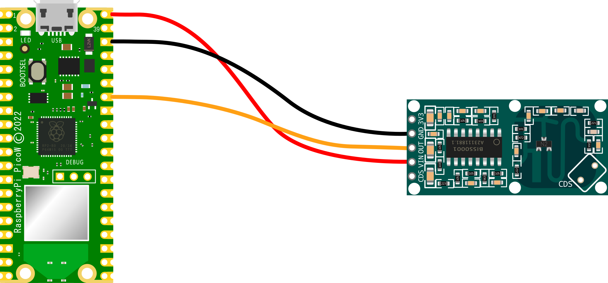
Of course we can simply use our favourite dupont connectors to do the job in the real world.
Code
The code below designates GP28 as the pin that the sensor’s out pin is connected to.
It defines a small function to blink the on-board LED and then two functions to operate if the sensor sees motion (it’s blinking time and printing out a notification) or if the environment around it is still.
import time
import machine

motion = machine.Pin(28,machine.Pin.IN)

# Define blinking function for onboard LED
def blink_onboard_led(num_blinks):
    led = machine.Pin('LED', machine.Pin.OUT)
    for i in range(num_blinks):
        led.on()
        time.sleep(.2)
        led.off()
        time.sleep(.2)

# What to do if motion detected
def moving():
    print("Motion detected")
    blink_onboard_led(1)

# What to do once motion ceased
def still():
    print("Everything is still")

while True:
    if motion.value():
        moving()
    else:
        still()
    time.sleep(1)
It really is a remarkably simple piece of code that we could add to as we wished to carry out other functions if it senses motion.
No comments:
Post a Comment