
This post is part of the book Raspberry Pi Computing: Analog Measurement which can be downloaded from Leanpub for free (or donate if you wish).
The Raspberry Pi is a marvel of connectivity. It’s 40 pin header and associated peripheral ports provide a spectacular range of options to interface with the world outside the Raspberry Pi. However, one feature that the Pi doesn’t have built in is the facility to accept an analog input.
Analog and Digital
Signals (or even information in general) can be broken down into two different types; Analog and digital.
Analog
An analog signal is one that has an infinitely variable range of values that can change over time.
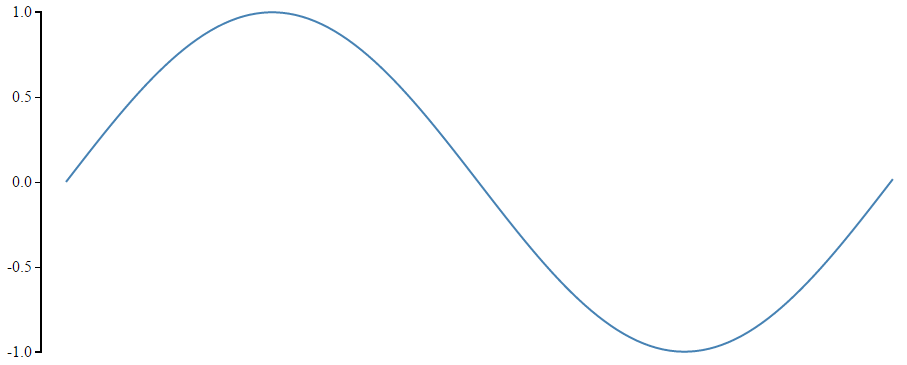
If we consider the question of how much light is shining outside we could imagine that the level of brightnesses varies between the blackness of a moonless night and a overcast sky to a cloudless day with the sun high in the sky.
These are rough approximations of dark and light, but between the two extremes is a range of brightness levels which are always changing. If we wanted to measure how bright it was at any particular time we could set ourselves a numeric range of 0 representing the middle of the night and 100 representing the middle of the day and the number that represented the brightness at any particular time would be somewhere between those two numbers. Typically in electronics an analog signal is a voltage that will be anywhere on that variable range between two limits. So straight up we can see that our analog sensor is going to be a device that provides an output value that varies between two extremes.
Digital
A digital signal represents information as discrete values.
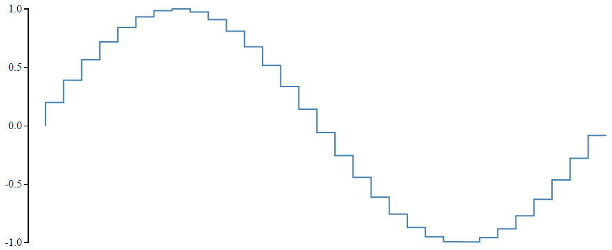
For example at it’s most fundamental the light level outside could be described as dark or light. Represented numerically this could be dark = 0 and bright = 1. While this is perfectly valid, we would often prefer to have a little more granularity in our measurement and so we can increase the number of discrete steps that represent light levels to match our expectations of the type of information we’re interested in. if we add another couple of levels, we could have light that was dark = 0, dim = 0.33, glowing = 0.66 and bright = 1. We can continue to improve the resolution of our numerical perception of the level of light in a process that is called Analog to Digital Conversion or ADC. Essentially creating steps that represent different levels of what would otherwise be a smooth transition.
The Boards
The Analog Sensor
While this project is more about the conversion of analog signals into digital ones, this project will use a Keyes KY-018 sensor based on a Light Dependent Resistor (LDR) to produce a variable resistance in the presence of different light levels. An applied voltage (from the Pi) returns a variable voltage from the LDR. It is this variable voltage that is then digitised with the ADC.

In essence there are a range of different sensors that could be used to produce an analog signal. I have successfully also connected the Keyes analog hall effect sensor (KY-035, which senses magnetic fields) and are will be others in that range that will work in the same way.
The Light Dependant Resistor (LDR or Photoresistor)
Our sensor will use an LDR to produce a variable resistance in the presence of different light levels.
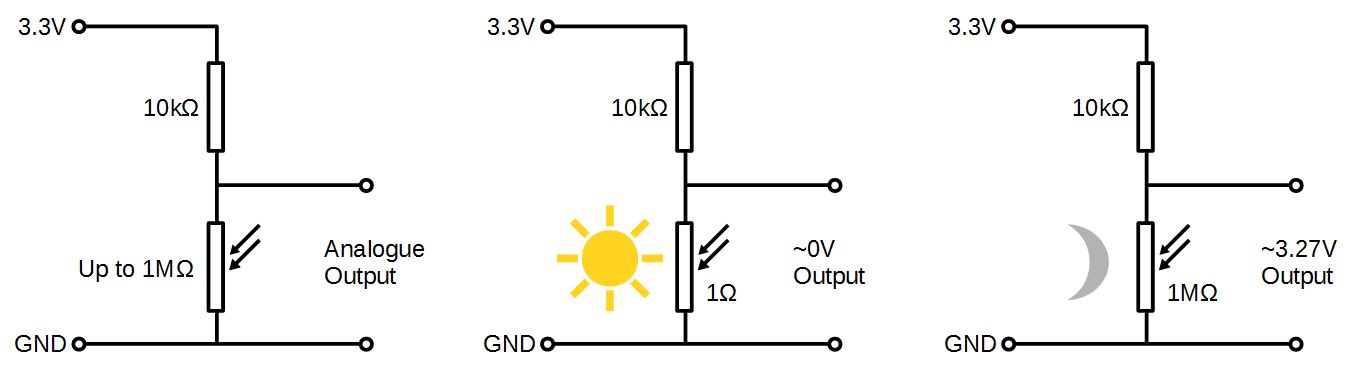
In the dark, their resistance is very high, sometimes up to 1MΩ, but when the LDR sensor is exposed to light, the resistance drops dramatically, even down to a few ohms, depending on the light intensity. LDRs have a sensitivity that varies with the wavelength of the light applied and are non-linear devices.
They are widely used in cameras, solar garden lights, clocks, mini night-lights, and a variety of light control devices.
Specifications from a typical LDR show that as illumination increases, the resistance of an LDR decreases.
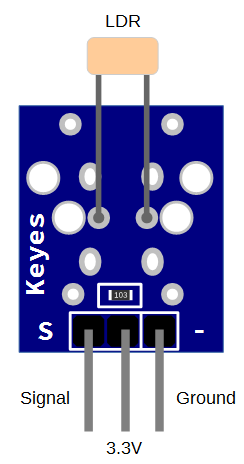
The Keyes KY-018 sensor board comprises an LDR and a fixed resistor with header pins for connecting the ground, the reference voltage (we will use the 3.3V from the Pi) and the sensors analog voltage output.
If we consider a simplified circuit of our sensor, the LDR in series with a fixed resistor allows the variation in resistance to develop a variation in output voltage.
Analog to Digital Conversion (ADC)
Luckily there are a wide range of options available to convert analog signals into digital ones. Therefore, people wanting to receive an analog signal with a Raspberry Pi can simply include a separate ADC into their project and it will work wonderfully. That’s what we’re going to do here using the ADS1015 from Adafruit. The ADS1015 has a 12bit resolution giving it the ability to convert an analog signal into one of 4096 discrete levels.
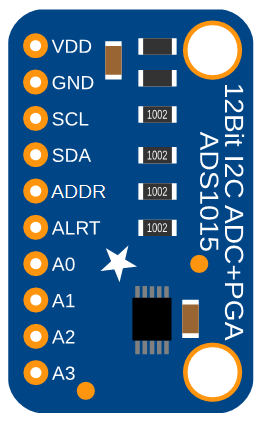
The ADS1015 Analog to Digital Converter
The ADS1015 is actually a component on our ADC board. This component is manufactured by integrated circuits manufacturer Texas Instruments. The circuit board that we’re using in the project is from Adafruit. It incorporates some interconnection circuity to make the signals as stable as practical and to provide a convenient physical interface (via header pins). The ADS1015 provides 12-bit (4096 levels) precision at up to 3300 readings per second (the rate is programmable). The board can be configured to accept four sensors of the type we will be using (single-ended), or two differential channels (which use two varying signals instead of a single signal and a ground). There is also a programmable gain amplifier built in with up to x16 gain, to help amplify smaller signals to the full range. The ADC can operate on a voltage range from 2V to 5V Which is applied to the VDD pin).
If all this sounds a bit ‘electrickery’, don’t worry. The aim here is to provide ourselves with enough information to get us started and if we feel like pressing on and learning more we will :-).
The ADS1015 will send the digital levels to the Pi via the I2C communications protocol. The address that this connection is made on can be changed to one of four options so you can have up to 4 ADS1015’s connected for up 16 sensor inputs!
Measure
Hardware required
- A Raspberry Pi (huge range of sources)
- ADS1015 Analog to Digital Converter from Adafruit.
- Female to Female Dupont connector cables (Deal Extreme or build your own!)
- Photoresistor module KY-018 from Keyes.
Connect
The LDR sensor board should be connected with ground pin (labelled ‘-‘) to a ground connector, the reference voltage pin (in the case of the board shown below the centre pin) to a 3.3V connector and the signal output pin (labelled ‘S’) to the A0 pin on the ADS1015 ADC.
The ADS1015 board should have the VDD pin connected to a 3.3V pin, the GND to a ground pin, the SCL pin to the SCL I2C connector on pin 5 and the SDA pin to the SDA I2C connector on pin 3 and lastly the ADDR pin should be connected to ground.
Both boards will support a connection to the ‘VDD’ and reference voltage connector of 5V, but this is not advisable for the Raspberry Pi as the resulting signal levels on the SDA connector may be higher than desired for the Pi’s input. This connection can be safely used with an Arduino board.
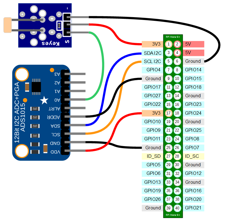
Connecting the sensor practically can be achieved in a number of ways. You could use a Pi Cobbler break out connector mounted on a bread board connected to the appropriate pins. But because the connection is relatively simple we could build a minimal configuration that will plug directly onto the pins using Dupont header connectors and jumper wire. The image below shows how simple this can be.

The follow on post that looks at testing the sensor is here.
For more info on using the Raspberry Pi or for a range of other free to download books (there are no catches) check out the list here.
For more info on using the Raspberry Pi or for a range of other free to download books (there are no catches) check out the list here.
No comments:
Post a Comment