The following description follows from the connection of an analog sensor and an analog to digital adapter here.
Since the ADS1015 uses the I2C protocol to communicate, we need to load the appropriate kernel support modules onto the Raspberry Pi to allow this to happen.
Firstly make sure that our software is up to date
Since we are using the Raspbian distribution there is a simple method to start the process of configuring the Pi to use the I2C protocol.
We can start by running the command;
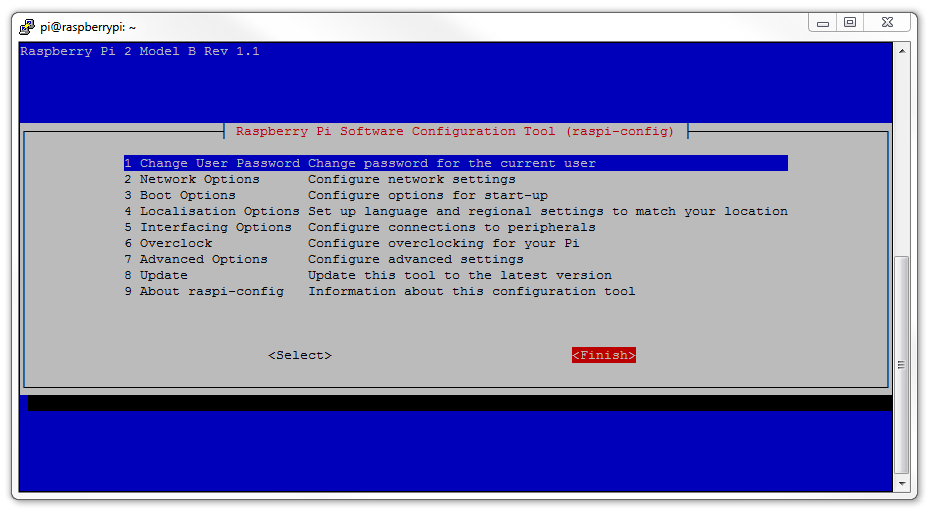
This will start the Raspberry Pi Software Configuration Tool.
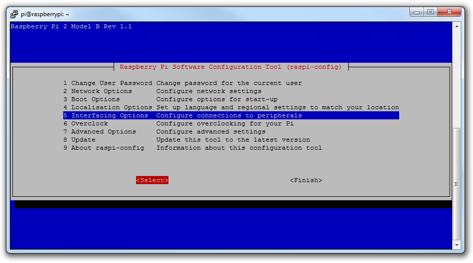
On the first page select the Interfacing Options with the arrow keys and then tab to select
Interfacing Options
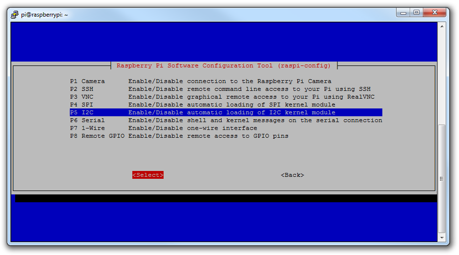
Then we select the I2C option for automatic loading of the kernel module;
Automatic Loading
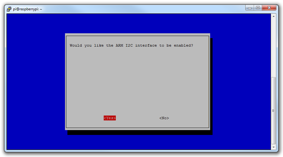
Would we like the ARM I2C interface to be enabled? Yes we would;
ARM I2C Interface Enabled
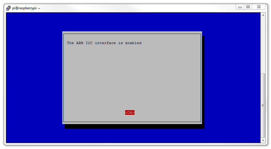
Press ‘OK’ to acknowledge that the interface is enabled.
Enabled!
Press tab to select ‘Finish’.
We’re Finished
There’s still some work to do to get things sorted. We need to check the /etc/modules file using:
Where we need to ensure that the following line is at the end of the file:
i2c-dev
Under some circumstances (depending on the kernel version we are using) we would also need to update the /boot/config.txt file. We can do this using;
Make sure that the following line is uncommented (the ‘#’ is removed from in front of the line) in the file;
dtparam=i2c_arm=on
The we should load tools for working with I2C devices using the following command;
… and now we should reboot to load the config.txt if we changed it earlier
We can now check to see if our sensor is working using;
This shows us that we have detected our ADS1015 on address ‘48’. The ADS1015 can support four different addresses as shown on page 17 of the data sheet. The address is selected by what the ADDR (short for address!) pin on the board is connected to;
ADDR PIN   ADDRESS
Ground     48
VDD        49
SDA        4A
SCL        4B
As we noted earlier, this means we can connect up to four ADS1015’s on the same I2C bus.
Now we want to install Python libraries designed to read the values from the ADS1015. The library we are going to use was designed specifically to work with the Adafruit ADS1015/ADS1115 ADCs. In carrying out this library development, Adafruit have invested a not inconsiderable amount of time and resources. In return please consider supporting Adafruit and open-source hardware by purchasing products from Adafruit!
Now we create a directory that we will use to download the Adafruit Python library (assuming that we’re starting from our home directory);
Now we will download the library into the adc directory (the following command retrieves the library from the github site);
Now that we’ve downloaded it, we can set it up. Run the following commands;
This will download and extract the tools. Then we can change into the examples directory
Now we can run the example program simpletest.py as follows;
This will start a program that will present a continuous reading of the four analog channels connected to the ADC.
Reading ADS1x15 values, press Ctrl-C to quit...
|0|1|2|3|
-------------------------------------
|5920|4704|4608|4608||5920|4576|4608|4656||7568|4640|4592|4656||14368|4656|4608|4672||15152|4656|4608|4656||14160|4608|4592|4672||13696|4608|4624|4640||14016|4608|4608|4704||8384|4608|4624|4672||4560|4592|4624|4656|
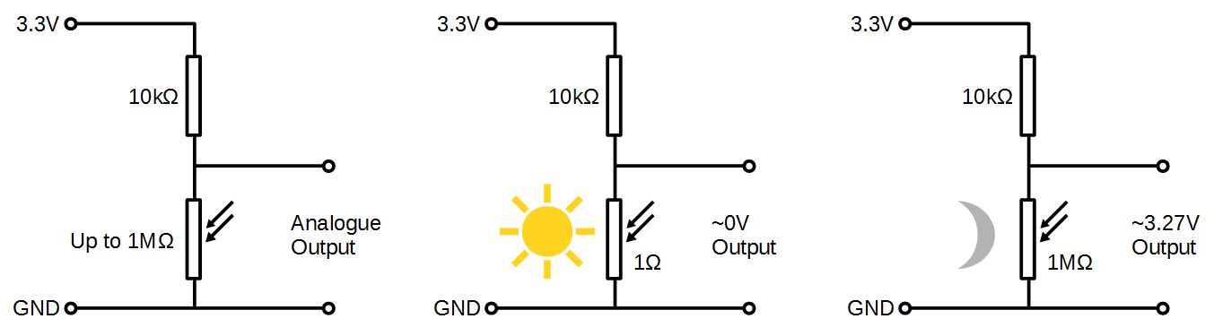
If we move the LDR about we should see that channel 0 varies up and down as the amount of light it receives varies. Success!
We should see that when the sensor is exposed to a stronger light the value decreases and when it gets darker the value increases.
If we remember back to our earlier diagram showing the type of connection this helps put the changes into context
LDR Sensor Output Voltage
We can press Ctrl-C to stop the program.
At this point we have successfully read and displayed an analog signal from a sensor using the Raspberry Pi.
For more info on using the Raspberry Pi or for a range of other free to download books (there are no catches) check out the list here.

No comments:
Post a Comment