
Ultrasonic Distance Measurement
This project will measure distance using an ultrasonic sensor module. We will use the JSN-SR04T sensor since it utilises a single waterproof send/receive audio module that will be useful for my particular application, but an alternative sensor called the HC-SR04 is a drop in replacement that combines the electronic and audio modules. It also breaks out the send and receive components which allows for measuring closer distances down to 2cm.
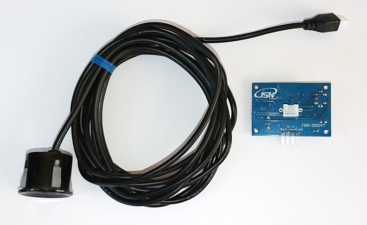
The JSN-SR04T Sensor
The JSN-SR04T is an ultrasonic ranging sensor that comprises an electronics module and a waterproof audio module connected by a long cable. It is designed to measure distance by sending out a high frequency pattern of pulses when triggered and to return a signal that corresponds to the length of time that it has taken for the pulses to travel out and be reflected back to the audio module.
JSN-SR04T Specifications
Specifications:
- Operating voltage: DC 5V
- Quiescent current: 5mA
- Total current work: 30mA
- Acoustic emission frequency: 40khz
- Farthest distance: 4.5m
- Shortest distance: 25cm
- Module size: 41mm x 28.5mm
- Resolution: about 0.5cm
- Angle: less than 50 degrees
- Working temperature: -10 to 70°C
Wiring:
- +5V (Power supply)
- Trig (Receives the trigger to operate)
- Echo (Signals time taken for audio send/receive trip)
- GND (Ground)
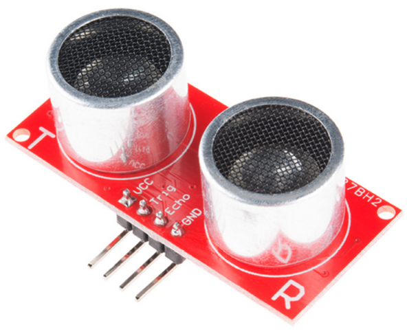
The device is touted as a drop-in replacement for the HC-SR04 which combines the electronics and audio modules and which separates the transmit and receive sensors.
Measure
Hardware required
- 1 x JSN-SR04T sensor
- 1k Ohm resister
- 2k Ohm resister
- Jumper cables with Dupont connectors on the end
- Solder
- Heat-shrink
Connect
For the sake of keeping the connecting pins together on the Pi’s GPIO block we will be connecting pins 4,6,8 and 10 to the JSN-SR04T electronics module. The following diagram provides a high level overview of the complete chain.
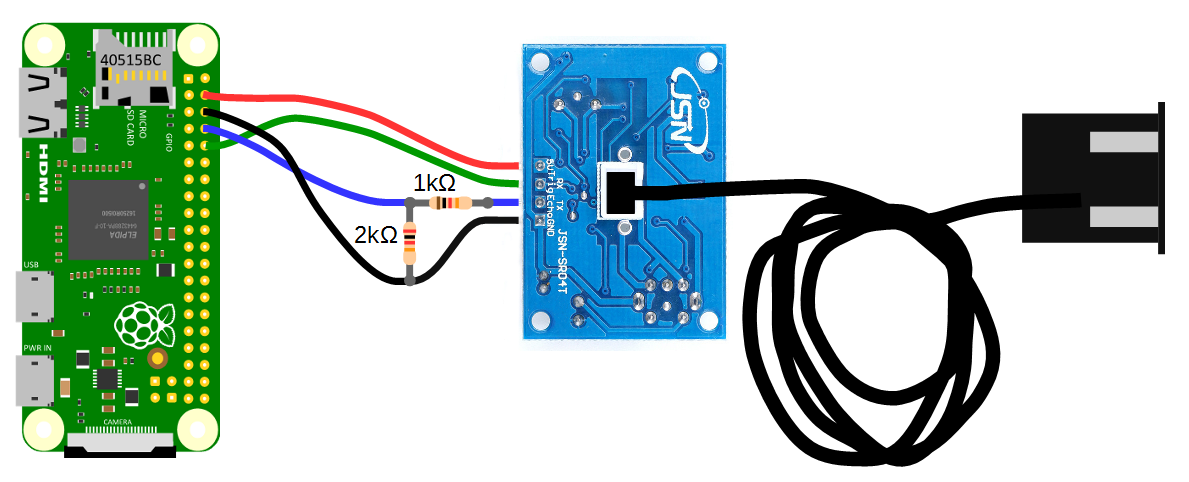
- Pin 4 connects directly to the +5V connector
- Pin 6 Connects directly to the GND connector, but is incorporated into the voltage divider for the Echo pin.
- Pin 8 connects to the centre of the voltage divider
- Pin 10 connects directly to the Trig connector.
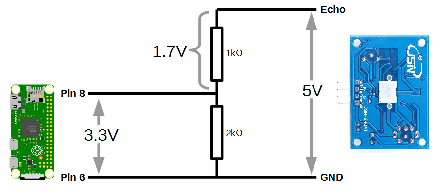
As we noted earlier, the Raspberry Pi provides general purpose digital input/output pins (called GPIO pins) that you can use for reading digital logic signals. In our case, we will want to apply the output signal from the ‘Echo’ pin to them. Unfortunately the output voltage from the Echo pin is 5V and the GPIO pins on the Raspberry Pi are only able to operate safely at voltage levels of 3.3V.
To safely apply the correct voltage to the Pi we can employ a voltage divider which divides the signal in a ratio corresponding to the resistance of two connected resistors. In the following diagram we can see that when a 5V signal is applied from the JSN-SR04T, 1.7V is dropped across the 1k Ohm resistor and 3.3V is across the 2k Ohm resistor.
Basic Operation
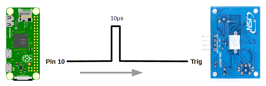
A pulse of at least 10us is applied to the trigger (Trig) pin of the electronics module.
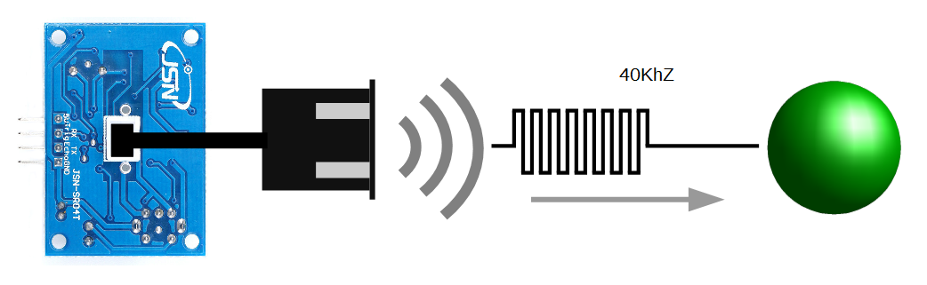
This will automatically generate 8 audio pulses at 40kHz from the audio transmitter / receiver module.
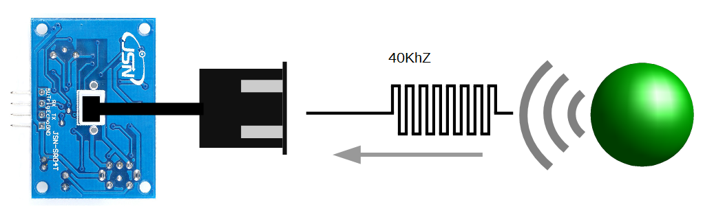
The 8 pulses will reflect off a surface and be received back at the audio module.
The electronics module will generate a signal from the Echo pin that corresponds to the time between the audio pulses being transmitted and the reflections being received. If no reflected audio is received, a signal of time, t = 38ms will be generated.
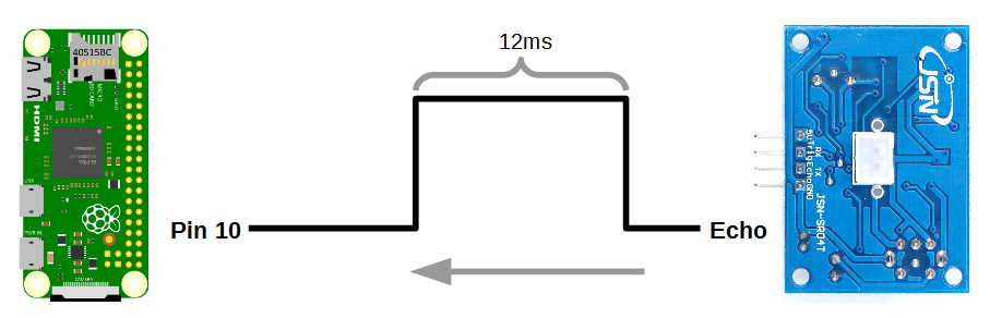
The distance from the audio module to the reflecting surface can be found by multiplying the time that the echo pin was high (represented as 12ms in the diagram)by the speed of sound (340m/s) and dividing by 2 (since the sound travelled out and back). Therefore;
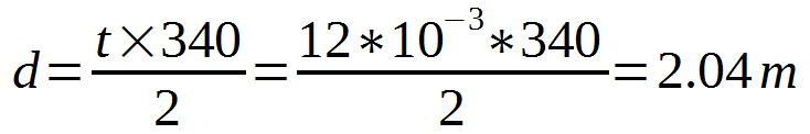
Our object is 2.04 metres away!
Test
The following python program can be saved onto our Pi as
distance.py and run from the command line using;#!/usr/bin/python
#encoding:utf-8
import RPi.GPIO as GPIO #Import GPIO library
import time #Import time library
GPIO.setmode(GPIO.BCM) #Set GPIO pin numbering
TRIG = 15 #Associate pin 15 to TRIG
ECHO = 14 #Associate pin 14 to Echo
print "Distance measurement in progress"
GPIO.setup(TRIG,GPIO.OUT) #Set pin as GPIO out
GPIO.setup(ECHO,GPIO.IN) #Set pin as GPIO in
while True:
GPIO.output(TRIG, False) #Set TRIG as LOW
print "Waiting For Sensor To Settle"
time.sleep(2) #Delay of 2 seconds
GPIO.output(TRIG, True) #Set TRIG as HIGH
time.sleep(0.00001) #Delay of 0.00001 seconds
GPIO.output(TRIG, False) #Set TRIG as LOW
while GPIO.input(ECHO)==0: #Check if Echo is LOW
pulse_start = time.time() #Time of the last LOW pulse
while GPIO.input(ECHO)==1: #Check whether Echo is HIGH
pulse_end = time.time() #Time of the last HIGH pulse
pulse_duration = pulse_end - pulse_start #pulse duration to a variable
distance = pulse_duration * 17150 #Calculate distance
distance = round(distance, 2) #Round to two decimal points
if distance > 20 and distance < 400: #Is distance within range
print "Distance:",distance - 0.5,"cm" #Distance with calibration
else:
print "Out Of Range" #display out of range
This program is available as
distance.py with the code samples that can be downloaded with the book from Leanpub.
When executed the sensor will settle and then start displaying the distance every two seconds.
Move the audio module about and confirm that it is operating as expected.
For more info on using the Raspberry Pi or for a range of other free to download books (there are no catches) check out the list here.
I would like to use your product to measure the level of my water tank, unsure of weather the signal will "bounce" off of the water correctly??
ReplyDeleteIt works for me. I have had this operating for over three years now without problem. A possible alternative if you were considering something would be a 'Time of Flight' (ToF) sensor. I'd like to try one of these one day.
DeleteFirst of all thanks a ton for the info and code you posted here :)
ReplyDeleteRelated to the above, I would like to use this system to control 2 submerged pumps via 2 separate relays (each inside a 10k liters cistern) so they will fill a secondary, 1000lt tank. Could I do that using the diagram described here? https://www.electronicshub.org/control-a-relay-using-raspberry-pi/ so that when the distance detected will be ~25cm the pumps will turn on and when the reading will be ~80cm they will turn off. Thanks much! :)
This would certainly be do-able with the link that you have provided, but I would hesitate to reccomend the ultrasonic distance measuring method as the mechanism to trigger the pumping. It might be a little 'fiddly' and I would probably reccomend using a simple imersion pump with a float switch that you could set up to switch on and off at the distances you mention via a little experimentation.
DeleteBest of luck