
This project will connect a 6 Degrees of Freedom (DoF) IMU to our Raspberry Pi Pico and demonstrate it’s use.
I've written this short explanation as part of the much larger book 'Raspberry Pi Pico Tips and Tricks'. You can download it for free from here.
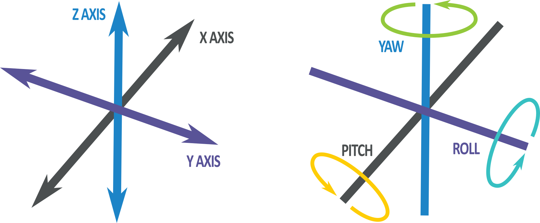
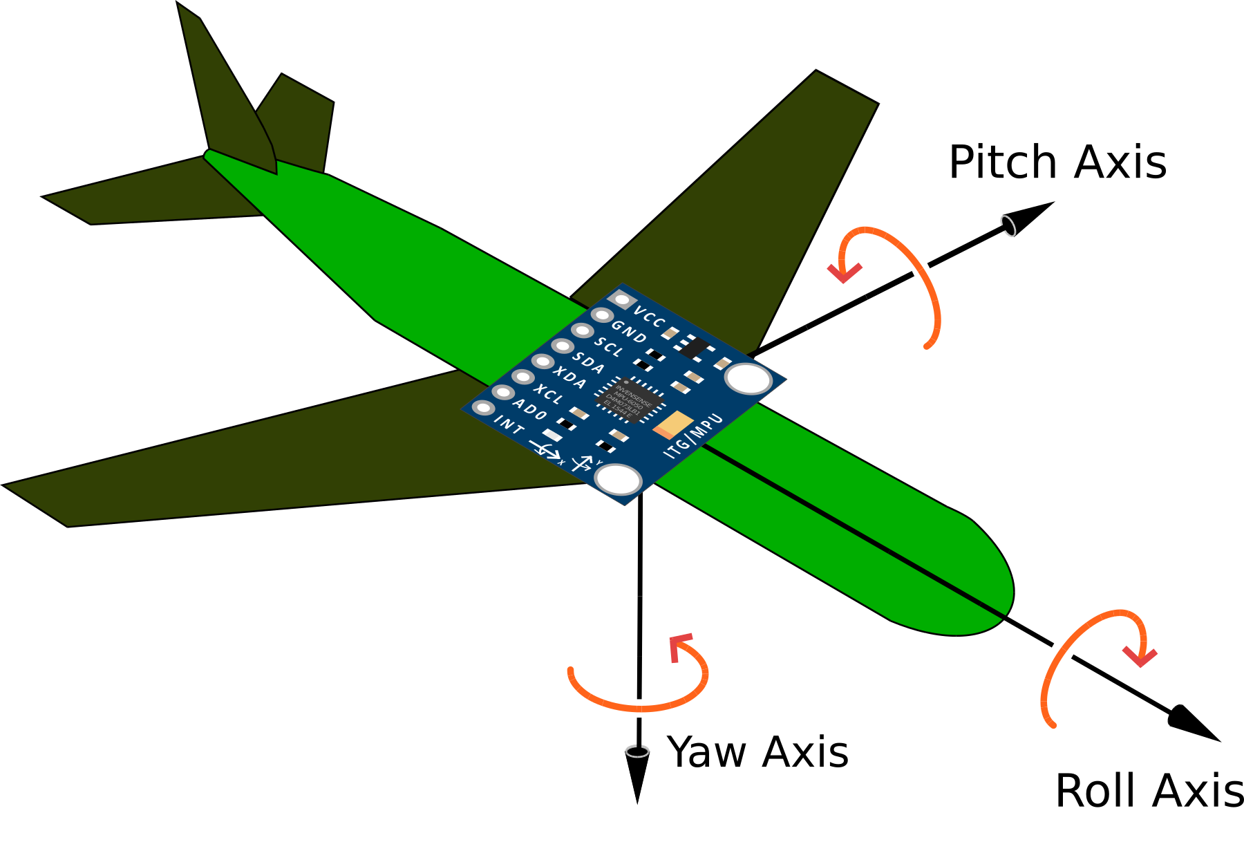
The IMU
An Inertial Measurement Unit, is a device that consists of one or more sensors that measure specific types of physical quantities, such as acceleration, angular velocity, and magnetic field strength. These sensors are typically arranged in a package that includes a microprocessor to process the sensor data and output the measured quantities in a usable form. IMUs are often used in applications that require precise measurements of motion, orientation, or position, such as in drones, robots, and virtual reality systems
IMUs have been around for several decades and have undergone significant development over time. Early IMUs were relatively simple devices that used mechanical sensors, such as gyroscopes and accelerometers, to measure motion and orientation. These sensors were often large and expensive, and the resulting IMUs were not very portable or practical for many applications.

In the last few decades, there has been a shift towards using microelectromechanical systems (MEMS) sensors in IMUs. These sensors are much smaller and more affordable than their mechanical counterparts, and they have greatly increased the portability and accessibility of IMUs.
IMU’s are typically defined by the numbers of ‘Degrees of Freedom’ (DoF) they are capable of measuring.
- 6 DoF: Includes a three axis accelerometer and a three axis gyroscope.
- 9 DoF: Includes the elements of a 6 DoF unit and a three axis magnetometer.
- 10 DoF: Includes the elements of a 9 DoF unit and a barometer.
In addition to the sensors themselves, modern IMUs also typically include a microprocessor that is capable of processing the sensor data and outputting it in a usable form. This allows the IMU to provide real-time measurements of motion, orientation, and position, which can be used in a variety of applications.
The unit we will connect to is capable of measuring 6 degrees of freedom.
3-axis Accelerometer
A MEMS (Microelectromechanical Systems) 3-axis accelerometer is a small, lightweight device that measures acceleration along three orthogonal axes (typically labeled as x, y, and z). It can be used to detect the magnitude and direction of gravitational acceleration, as well as any additional acceleration that may be caused by movement or vibration.
Accelerometers are commonly used in a variety of applications and can be used to detect the orientation of the device relative to a reference frame, to measure the acceleration of the device during movement, or to detect and respond to impacts or other types of mechanical shock.
MEMS accelerometers typically use a small mechanical structure, such as a proof mass, that is suspended on a flexible beam or membrane. When the device is subjected to acceleration, the proof mass is displaced from its equilibrium position, and this displacement is detected by a sensor, such as a capacitive or piezoresistive transducer. The sensor output is then processed by an electronic circuit to determine the magnitude and direction of the acceleration.
MEMS accelerometers are often small and inexpensive, and they can operate over a wide temperature range. They are also relatively low power and have a fast response time, which makes them well-suited for use in portable and mobile applications.
3-axis Gyroscope
A MEMS (Microelectromechanical Systems) 3-axis gyroscope is a small, lightweight device that measures angular velocity along three orthogonal axes (typically labeled as x, y, and z). It can be used to detect the rate of rotation around these axes, and can be used to determine the orientation of the device relative to a reference frame.
Gyroscopes are commonly used in a variety of applications that require precise measurement of motion or orientation, such as in drones, robots, and virtual reality systems. They can be used to stabilize the motion of a device, to navigate through unknown environments, or to track the orientation of the device over time.
MEMS gyroscopes typically use a small mechanical structure, such as a spinning rotor or a vibrating element, that is suspended on a flexible beam or membrane. When the device is subjected to angular velocity, the rotor or vibrating element responds by changing its position or motion, and this change is detected by a sensor, such as a capacitive or piezoresistive transducer. The sensor output is then processed by an electronic circuit to determine the magnitude and direction of the angular velocity.
MEMS gyroscopes are often small and inexpensive, and they can operate over a wide temperature range. They are also relatively low power and have a fast response time, which makes them well-suited for use in portable and mobile applications. However, they are subject to drift over time, which can limit their accuracy in certain applications.
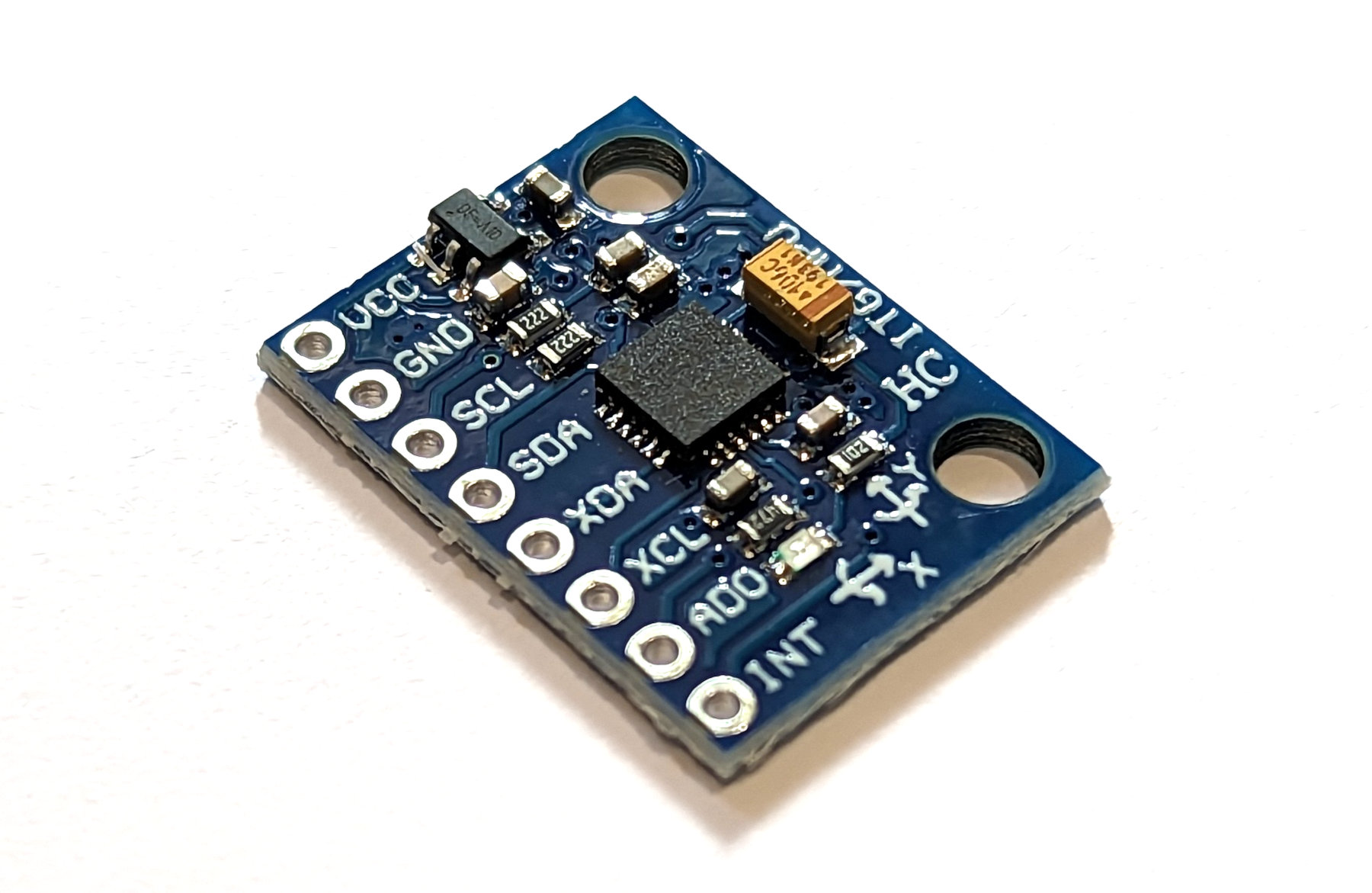
The GY-521 IMU module using a MPU-6050
The GY-521 module is a breakout board for the MPU-6050. This is a 6-axis IMU that includes a 3-axis accelerometer and a 3-axis gyroscope. It is produced by InvenSense and is commonly used in a variety of applications that require precise measurements of motion, orientation, or position.
The accelerometer component of the MPU-6050 measures linear acceleration in the x, y, and z axes. It can be used to detect the magnitude and direction of gravitational acceleration, as well as any additional acceleration that may be caused by movement or vibration. The accelerometer measures the rate of change of velocity over time. It is sensitive to changes in motion and can be used to detect the direction and magnitude of acceleration, as well as changes in orientation.
The gyroscope component of the MPU-6050 measures angular velocity in the x, y, and z axes. It can be used to detect the rate of rotation around these axes, and can be used to determine the orientation of the device relative to a reference frame. The gyroscope measures angular velocity, which is the rate of change of orientation over time. It is sensitive to changes in rotational motion and can be used to detect the direction and magnitude of rotation, as well as changes in orientation.
The MPU-6050 also includes a built-in temperature sensor and a digital motion processor (DMP) that can be used to process the sensor data and output it in a usable form. The MPU-6050 communicates using an I2C or SPI interface, and it can be configured and controlled using register settings.
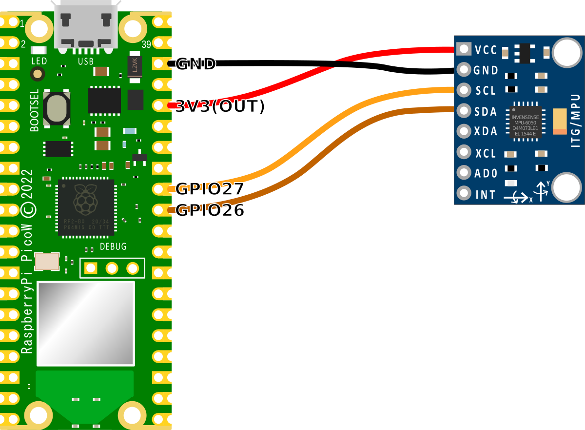
Connecting the GY-521 to the Raspberry Pi Pico
The connection is fairly simple with only four connecting wires being required. Power, ground, Serial CLock line (SCL) and Serial DAta line (SDA). The following connections are used for this example
- Connect the GY-521’s SDA (data) pin to the Pico’s I2C1 SDA (pin 31, or GPIO26) on the Pico (Brown).
- Connect the GY-521’s SCL (clock) pin to the Pico’s I2C1 SCL (pin 32, or GPIO27) on the Pico (Orange).
- Connect the GY-521’s VCC (power) pin to the Pico’s 3V3(OUT) (pin 36) power pin.
- Connect the GY-521’s GND (ground) pin to the Pico’s GND (pin 38) pin.
An important point to note when we are connecting our Pico is that because the RP2040 microcontroller has two I2C controllers, we need to ensure that we define which controller we are using in the code. I2C0 = id 0 and I2C1 = id 1. This is set in the following lines in the MicroPython code;
In our case, since we are using GPIO26 and GPIO27 for the SDA and SCK connections we are using I2C Controller 1.
Code
The values from the IMU are accessed via two pre-built MicroPython modules (imu.py and vector3d.py). These have been published on GitHub. To make use of the module we will need to download them from GitHub and then copy them over to our Pico. I found this most easily accomplished by first downloading the files to the main computer and then going File >> Open on Thonny and selecting the appropriate file. From there go File >> Save as… and select the Pico as the location to save the file (making sure to save it with the appropriate name).
The printed values from the code below represent the accelerometer and gyroscope readings of the MPU-6050 IMU in 3-dimensional space.
In this code, the x, y, and z values represent the readings in the respective axes. Positive values indicate that the IMU is accelerating or rotating in the positive direction of the respective axis, while negative values indicate that it is accelerating or rotating in the negative direction.
import time
from machine import I2C, Pin
from imu import MPU6050

# Set up I2C communication with the MPU-6050
i2c = I2C(1, sda=Pin(26), scl=Pin(27), freq=400000)

# Create an MPU6050 object with the I2C interface
imu = MPU6050(i2c)

# Set the full-scale range of the accelerometer (in g)
imu.accel.full_scale_range = 2

# Set the update rate of the loop (in Hz)
UPDATE_RATE = 10

# Main loop
while True:
    # Read the accelerometer and gyroscope values
    accel = imu.accel
    gyro = imu.gyro

    # Print the values to the terminal
    print("Acceleration x: {:+5.2f} y: {:+5.2f} z: {:+5.2f}    gyroscope x: {:+7.\
2f} y: {:+7.2f} z: {:+7.2f}".format(
        accel.x, accel.y, accel.z, gyro.x, gyro.y, gyro.z), end='\r')

    # Wait a moment before reading again
    time.sleep(1.0 / UPDATE_RATE)
The time and machine modules are imported, along with the MPU6050 class from the imu module.
The I2C interface is set up using the I2C class from the machine module, with the sda and scl pins connected to pins 26 and 27 on the Raspberry Pi, respectively. The frequency of the I2C bus is set to 400000 Hz.
An MPU6050 object is created with the I2C interface. This object will be used to communicate with the IMU and read the accelerometer and gyroscope values.
The full-scale range of the accelerometer is set to 2 g. This determines the maximum range of the accelerometer readings, with higher values corresponding to a larger range.
The main loop begins and the accelerometer and gyroscope values are read using the accel and gyro properties of the MPU6050 object. These properties are objects that contain the x, y, and z components of the acceleration and angular velocity vectors, respectively.
The print section outputs the values to the terminal in a format that makes it easy to read (but not necessairly easy to write!)
No comments:
Post a Comment