
The Raspberry Pi Pico can be used to provide lighting control to create effects and custom illumination via individually addressable LEDs that can be combined in a range of configurations. The applications could range from a simple colour changing accent light to a wearable display to a light sabre.
I've written this short explanation as part of the much larger book 'Raspberry Pi Pico Tips and Tricks'. You can download it for free from here.
What are addressable LEDs?
Addressable LEDs are lights that have unique controllers built in that allow us to adjust the properties of individual LEDs or groups of them ganged together in strips, matrices or other patterns. The ability to control a specific LED is why they are referred to as ‘addressable’. Having this function available allows us to create different effects for a single LED either on its own or as part of a larger display.
There are a variety of configurations for addressable LEDs. As well as the different pattern configurations (strips, matrices etc.) they can come in different densities, colour, weather proofing, and connectivity options.
The most significant feature of addressable LEDs is the type of integrated controller chip that they use. The three most common are;
- WS2811
- WS2812B
- WS2813
WS2811
The WS2811 is normally found in 12V installations. 12V is preferable if we want to connect up longer lengths of LEDs to reduce the effects of voltage drop with distance. This aids in providing better colour consistency.
As we are going to be using the Pico, the added complexity of using a different voltage source for the LEDs and the Pico is not going to be an advantage.
One of the most popular brands of addressable LEDs are made and distributed by Adafruit and are called NeoPixels. They have put a lot of effort into developing and supporting this product and I thoroughly recommend that you take a look.
WS2812B and WS2813
There is an older version of the WS2812B called the WS2812. The older version utilised a six pin connection which made connection slightly more complicated, and the newer version improved the mechanical properties of the package along with better heat dissipation, higher brightness and reverse power protection.
The WS2812B is a less advanced option than the WS2813. While both will typically operate from a 5V source, the WS2813 has a higher refresh rate (2000Hz vs 400Hz) and it includes a backup signalling channel which will make larger arrays of the LEDs more tolerant to individual failure.
The recommended power injection interval on the WS2812B is higher (5m vs 2.5m for the WS2813) which makes longer runs when configured in strips easier.
How do addressable LEDs work?
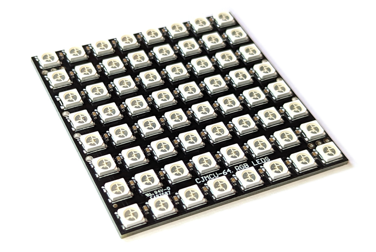
Each addressable LED includes the LED proper (typically a 5050 RGB model) which is a combination of three separate Red, Green and Blue (RGB) LEDs in a 5mm x 5mm package with a controller IC (the aforementioned WS2812B or WS2813).
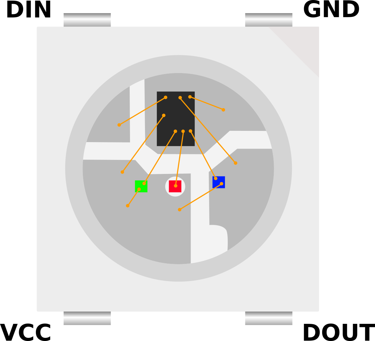
Each package has four pins – VCC, Ground, DIN (Data IN), and DOUT (Data OUT). The controlling connection from our Pico goes to the DIN pin and follow on LEDs are daisy chained from the initial devices DOUT pin to the follow on devices DIN. Thus, the controlling signal only requires a single wire from our Pico (Although it will still require power in the form of VCC (5V) and ground).
Each separate red, green, and blue LED in the package can be set to shine at one of 256 brightness levels. The combination of those three colours at different levels of brightness allows for the generation of the full colour spectrum. The signal sent from our Pico will be a sequence of RGB combinations which will go to the first connected LED. This receives the first set of RGB levels and passes the remainder through to the follow on LED. This in turn receives the next set of levels and passes on the remainder etc, etc, until the end of the line (signals or LEDs) is met.
Signal Voltage Level
While we have discovered above that there are 12V and 5V versions of the LEDs that can be used for these applications, the 5V versions are the most prevalent. However, if we look at the datasheets for the devices (WS2812 WS2812B, WS2813) we can see that they generally have a fairly loose range of supply voltages (VCC) that will power them, but the voltages for the signal line on DIN are a proportion of the supply voltage. A signal ‘high’ is 0.7 x VCC and a ‘low’ is 0.3 x VCC.
Meaning that if we were supplying exactly 5V to power one of the LEDs, we would require a voltage of 3.5V for the LED to recognise the signal as a logical ‘high’. “Hang on” I hear you say. “Our Raspberry Pi Pico will only send out a 3.3V signal as a ‘high’ when it is connected to a GPIO pin”. Yep. Well spotted. So what’s that all about?
Well… The required signal levels in these cases are a little like the pirate’s code. It turns out that they are more of a ‘guideline’ than a hard and fast rule.
I have yet to come across an addressable LED device that didn’t work with 3.3V signalling if VCC is set at 5V. That’s not to say that it won’t happen, but at the time of writing, that has been my experience.
If we wanted to make sure that we were being faithful to the requirements of the datasheet we could employ the services of a ‘level shifter’ or ‘logic level converter’ that will change our logic levels from one voltage to another.
Power Requirements
Each individual LED can draw up to 60mA of current. That’s not a huge amount in the scheme of things, but because addressable LEDs are typically packaged as strips or matrices, if we multiply that current draw by the possible number of LEDs in a connection, the value starts to be come significant.
For instance, a 1m strip with 30 LED’s could potentially draw up to 1.8A of current. That’s quite a lot and to be honest, it’s a worst case scenario. For general use where we would be varying our colours and brightness to make pretty patterns, we can probably work on a rule of thumb that 20mA per LED is about right.
Our Pico has a direct connection from the USB connector to the VBUS connector (where we are taking our 5V supply from for our LEDs) so that means that we are dependant on our power supply to our Pico in terms of managing the appropriate amount of power if we are feeding our LEDs from the Pico.
If we were using a larger number of connected LEDs it might be necessary to divide your strip into different sections and connect separate power supplies. This could be because you need a certain amount of current to drive the LEDs or it could be because of the voltage drop that will occur over longer distances due to the resistance of the copper connecting wires.

Important points to note when doing this is that the ground wires are all connected together and the signal chain is contiguous, but the positive power line is separated into its different sections.
Connecting the addressable LEDs
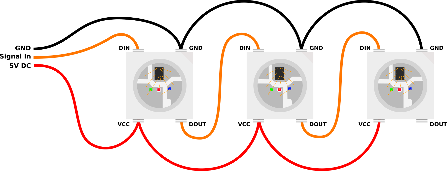
As described above, the connection will depend a little on what LED module you are using and whether or not you determine that you might need a logic level converter, but for 95% (I’m speculating wildly with this figure BTW) of connections you should be able to simply connect as follows;
Keeping in mind that we are utilising the GPIO26 pin in this example for simplicity’s sake. You should be able to use any GPIO pin. You will need to adjust the pin number in the code samples below however.
How do we talk to our addressable LEDs?
The LEDs are accessed via a pre-built MicroPython module. This has been published on GitHub by Blaž Rolih. To make use of the module we will need to download it from GitHub and then copy it over to our Pico. I found this most easily accomplished by first downloading the file to the main computer and then going File >> Open on Thonny and selecting the appropriate file. From there go File >> Save as… and select the Pico as the location to save the file (making sure to save it with the appropriate name (neopixel.py)).
Code
Scroll a red LED through all the pixels
from utime import sleep
# We are using https://github.com/blaz-r/pi_pico_neopixel
from neopixel import Neopixel

NUMBER_PIXELS = 64
STATE_MACHINE = 0
LED_PIN = 26

strip = Neopixel(NUMBER_PIXELS, STATE_MACHINE, LED_PIN, "GRB")

# Color RGB values
red = (255, 0, 0)
off = (0,0,0)

delay = .1
while True:
    for i in range(0, NUMBER_PIXELS):
        strip.set_pixel(i, red)
        if i > 0: strip.set_pixel(i-1, off)
        if i == 0: strip.set_pixel(NUMBER_PIXELS-1, off)
        strip.show()
        sleep(delay)
This code (led-red-run.py) is available to download (at no cost) as an extra from Leanpub when you download the book
Run two LEDs around the outside of a 8 x 8 matrix.
from utime import sleep
# We are using https://github.com/blaz-r/pi_pico_neopixel
from neopixel import Neopixel

NUMBER_PIXELS = 64
STATE_MACHINE = 0
LED_PIN = 26

strip = Neopixel(NUMBER_PIXELS, STATE_MACHINE, LED_PIN, "GRB")

# Color RGB values
red = (255, 0, 0)
off = (0,0,0)

delay = .1
while True:
    for i in range(0, 8):
        strip.set_pixel(i, red)
        if i > 0: strip.set_pixel(i-1, off)
        if i == 0: strip.set_pixel(63, off)
        strip.set_pixel(i*8, red)
        if i > 0: strip.set_pixel((i-1)*8, off)
        strip.show()
        sleep(delay)
    for i in range(1, 8):
        strip.set_pixel(56+i, red)
        if i > 1: strip.set_pixel(56+(i-1), off)
        if i == 1: strip.set_pixel(56, off)
        strip.set_pixel(((i+1)*8)-1, red)
        strip.set_pixel(((i)*8)-1, off)
        #if i > 1: strip.set_pixel(((i-1)*8)+7, off)
        strip.show()
This code (led-8x8-outside.py) is available to download (for free) as an extra from Leanpub when you download the book
There are a couple more code samples available for download from Leanpub.
led-8x8-squares.pywhich cycles squares in and out of an 8x8 matrix.led-8x8-squares.pywhich cycles lines to and fro on a 8x8 matrix.led-random.pywhich flashes random colours on random pixels in a matrix or a strip (just set the number of pixels).
No comments:
Post a Comment