This project will measure the presence of types of gas in the air using one of the MQ series of sensors.
I've written this short explanation as part of the much larger book 'Raspberry Pi Pico Tips and Tricks'. You can download it for free (or donate if you wish) from here.
The Sensor
MQ-2 Gas Sensor
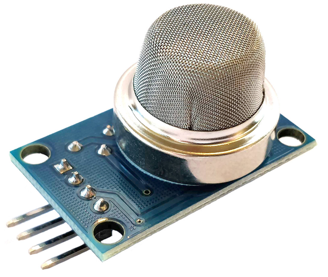
The MQ-2 is a commonly used gas sensor in MQ sensor series. It is what’s referred to as a Chemiresistor as the detection is based upon change of resistance of the sensing material when the gas comes in contact with a Metal Oxide Semiconductor (MOS). The value of the analog signal output varies as the gas concentration varies.
Different metal oxides have different chemiresistive properties allowing them to sense different gasses.
The most obvious feature of the sensor is the surrounding layer (actually two layers) of stainless steel mesh called an ‘anti-explosion network’. This is present to make sure that the heater element inside the sensor doesn’t cause an explosion while it is in the presence of flammable gasses. It also acts as a filter to allow only gases to pass through to the sensor.
The MQ-2 sensor which we will be using can detect LPG, butane, propane, methane, alcohol, Hydrogen and smoke concentrations from 200 to 10000ppm.
There are a wide range of sensors in the MQ series that can detect the presence of different gasses.
The sensor we will be using is mounted on a circuit board for ease of connection. We provide it with a 3.3VDC supply and it returns an analog signal that varies in proportion to the concentration of our target gas. That signal can vary between 0VDC and 3.3VDC. The board also includes a digital output option, but this is designed to provide a breakpoint level of gas, rather than a value. The variable resistor (potentiometer) on the board allows this breakpoint to be varied.
MQ-2 Sensor Board Underside
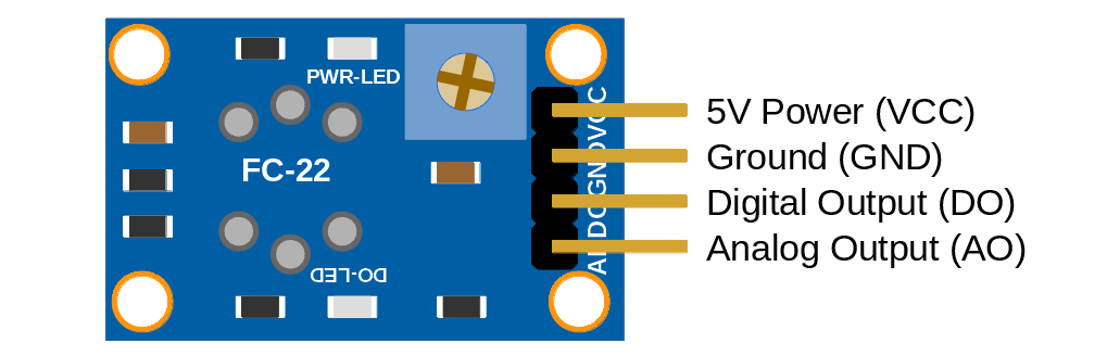
The connections on the board are as follows
VCC: Is the power input. This will require 3.3VDC in our case, but it can actually accept anywhere from 2.5VDC to 5VDC)
GND: Is the ground pin
DO: Provides the digital output set by the potentiometer
AO: is the analog output signal.
It is this analog voltage that is then digitised with our Analog to Digital Converter (ADC) that is built into the microcontroller.
Connect Everything Up
We will want to connect;
VCC on the MQ-2 to the 3V3 pin (36) on the Pico
GND on the MQ-2 to the Ground pin (38) on the Pico
A0 on the MQ-2 to ADC0 pin (31) on the Pico
The power and ground pins are fairly self explanatory, and because the MQ-2 has an analog output that will vary from the applied voltage to 0V, we will apply this to one of our Analog to Digital Converter (ADC) pins. In this case ADC0 on pin 31.
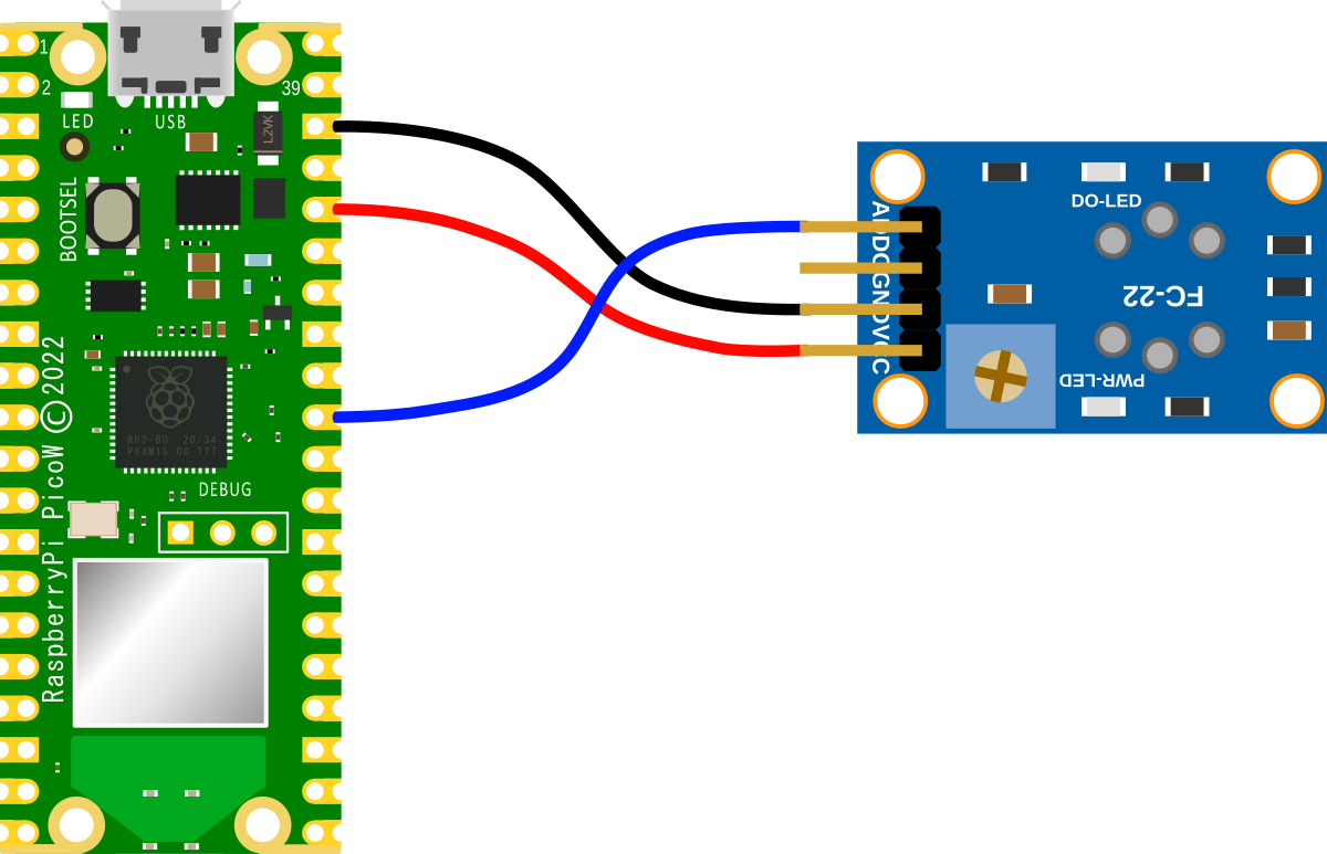
MQ-2 connection to the Pico
Connecting the sensor practically can be achieved in a number of ways. But because the connection is relatively simple we can build a minimal configuration that will plug directly onto the pins using Dupont header connectors and jumper wire.
Code
The following code will read the value from the MQ-2 and convert that to the effective voltage that should be present on the analog pin. It will print this out every second.
importmachineimporttimemq2=machine.ADC(26)conversion_factor=3.3/(65535)whileTrue:voltage=mq2.read_u16()*conversion_factorprint("Output voltage is",voltage)time.sleep(1)

No comments:
Post a Comment