
Distance Measurement using Time of Flight Sensor
What is a Time Of Flight Sensor?
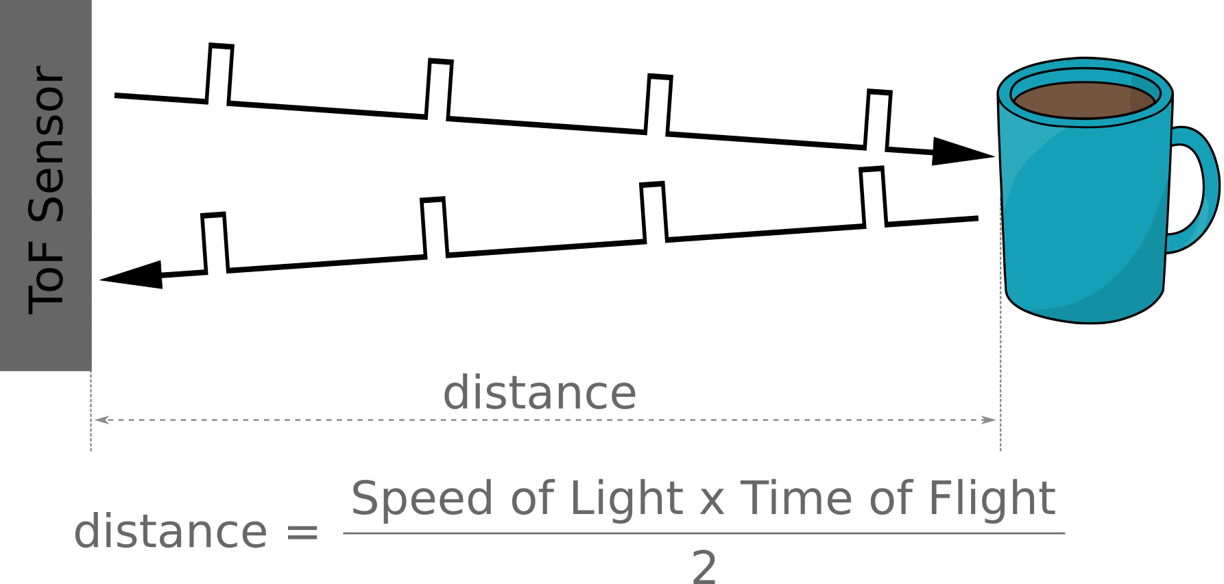
A Time of Flight (ToF) sensor measures the time it takes for a signal to travel a distance through a medium. This is a deliberately broad definition since there are different ways to carry this out depending on the application. For the purposes of our explanation we are going to be describing a sensor that measures the time elapsed between the emission of a pulse of light, its reflection off an object, and its return to the ToF sensor.
In this case, the sensor itself is an extremely compact device that is popular for applications in robotics and cameras.
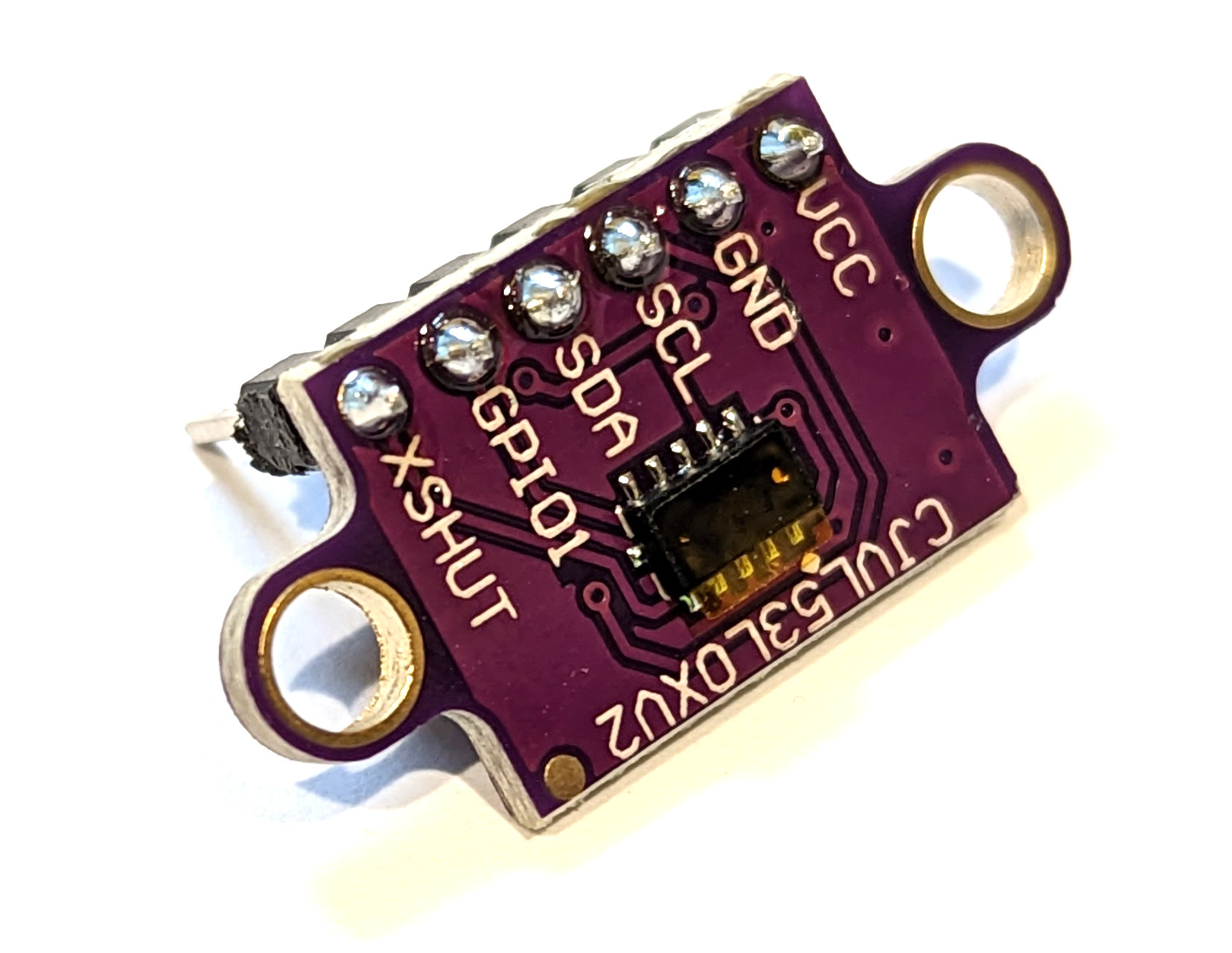
The sensor we will be using is a VL53L0X Time-of-Flight laser-ranging module which can provide an accurate distance measurement to objects up to 2m away.
The VL53L0X uses a 940nm (infrared) Vertical Cavity Surface-Emitting Laser which is invisible to the human eye. The output is engineered to remain within Class 1 laser safety limits and as such is safe under all operating conditions. Have a read of the vl53l0x Datasheet for all the good info.
I've written this short explanation as part of the much larger book 'Raspberry Pi Pico Tips and Tricks'. You can download it for free (or donate if you wish) from here.
How does a Time Of Flight Sensor Work?
ToF sensors use a laser to emit infrared light. The light reflects off any object it strikes and returns to the sensor. Based on the time difference between the emission of the light and its return it is able to measure the distance between the object and the sensor.
The VL53L0X precisely measures how long it takes for emitted pulses of infrared laser light to reach the nearest object and be reflected back to a detector, so it can be considered a tiny, self-contained lidar system. The sensor can measure distances of up to 2m with 1 mm resolution, but its effective range and accuracy depend on ambient conditions and target characteristics like size and degree of reflectivity. The sensor’s accuracy can vary from ±3% at best to over ±10% in less optimal conditions.
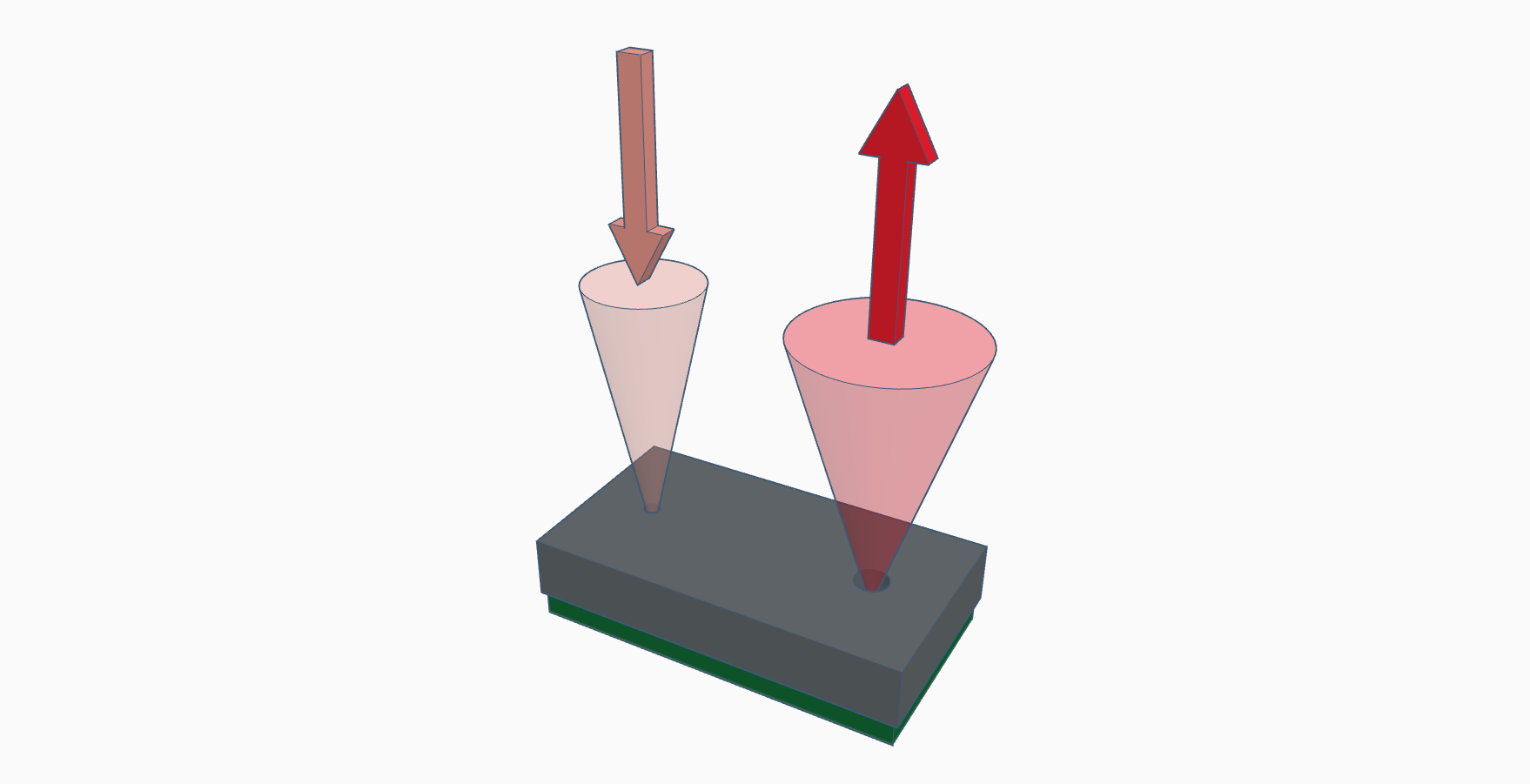
The beam of the emitted light is quite narrow and the orientation of the sensor and the measured object will be factors in recording accurate values. This is also a positive thing since the narrow light source is good for determining distance of only the surface directly in front of it. Unlike audio based systems that utilise ultrasonic waves, the ‘cone’ of sensing is very narrow.
How is a Time Of Flight Sensor Controlled?
The sensor is controlled via I2C, but we can abstract the complexities of this via a prebuilt MicroPython module. This was initially developed by Robin Matzner and was then adapted by Kevin McAleer. To make use of the module we will need to download it from GitHub and then copy it over to our Pico. I found this most easily accomplished by first downloading the file to the main computer and then going File >> Open on Thonny and selecting the appropriate file. From there go File >> Save as… and select the Pico as the location to save the file (making sure to save it with the appropriate name (vl53l0x.py))
Because of the abstraction afforded by the library, the adjustments that we can make are nicely simplified.
Range Timing Budget
The first thing we can adjust is the range timing budget. This is set up to manage the ‘ranging phase’ of the measurement where, several pulses are emitted, then reflected back by the target object, and detected by the receiving array. The typical timing budget for a range timing budget is 33ms with 200ms being used for high accuracy and 20ms recommended for high speed. This is changed in the MicroPython code via the line;
Pulse Period
The other major adjustment that we can introduce is to the period of the pulse that is send out. The shorter the pulse, the better for closer measurements, the longer the pulse, the better for more distant measurement. There are two period ‘types’, Pre Range (Type 0) and Final Range (Type 1). Longer periods increase the potential range of the sensor. Valid values are even numbers only. These can be set in the MicroPython code via the lines;
The Pre Range settings can go from: 12 to 18 (default is 14) and the Final Range settings can go from 8 to 14 (default is 10).
Connecting a Time Of Flight Sensor Up to the Pico
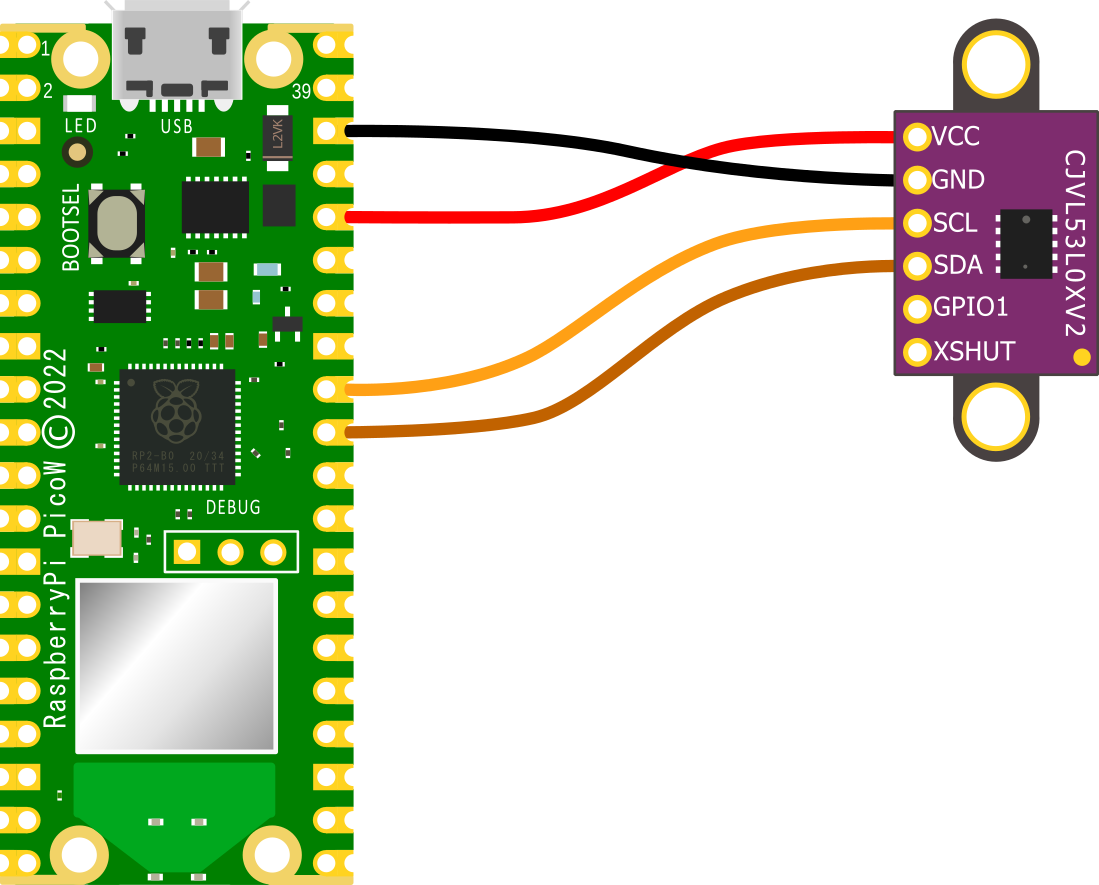
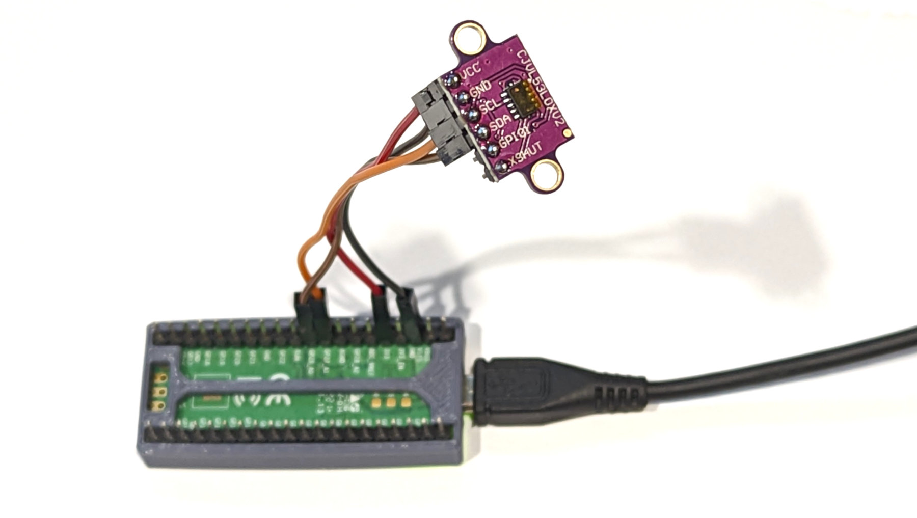
The connection is fairly simple with only four connections being required. Power, ground, Serial CLock line (SCL) and Serial DAta line (SDA). The following connections are used for this example;
- VL53L0X GND to Ground (pin 38) on the Pico (Black)
- VL53L0X VCC to the 3V3(OUT) (pin 36) on the Pico (Red)
- VL53L0X SCL to I2C1 SCL (pin 32) on the Pico (Orange)
- VL53L0X SDA to I2C1 SDA (pin 31) on the Pico (Brown)
When selecting the I2C connections on the Pico, because the RP2040 microcontroller has two I2C controllers we need to ensure that we define which controller we are using in the code. I2C0 = id 0 and I2C1 = id 1. This is set in the following lines in the MicroPython code;
The best place to ensure that we have the id correctly identified is on the pinout.
Assuming that we have header pins soldered onto our Pico and the ToF sensor, the easiest ways to make a connection is via Dupont connectors.
The only other point to note is that there are reports of some inconsistent measurements if the XSHUT pin is left ‘floating’ (i.e, not tied to a low (ground) or high pin). I haven’t experienced this myself, but if you’re seeing something that you can’t explain, this could be worth investigating
Code
The code below is largely that written by Kevin McAleer and published on GitHub. However, it is adapted to provide for the connection as described above and it is tuned to optimise for longer distance readings. Likewise I have included a small piece of code to average out the readings to improve consistency.
import time
from machine import Pin, I2C
from vl53l0x import VL53L0X
print("setting up i2c")
sda = Pin(26)
scl = Pin(27)
id = 1

i2c = I2C(id=id, sda=sda, scl=scl)
print(i2c.scan())
print("creating vl53lox object")
# Create a VL53L0X object
tof = VL53L0X(i2c)
# the measuting_timing_budget is a value in micro seconds, the
# longer the budget, the more accurate the reading. (originally 40000)
budget = tof.measurement_timing_budget_us
print("Budget was:", budget)
tof.set_measurement_timing_budget(100000)
# Sets the VCSEL (vertical cavity surface emitting laser) pulse period
# for the given period type (VL53L0X::VcselPeriodPreRange or
# VL53L0X::VcselPeriodFinalRange) to the given value (in PCLKs).
# Longer periods increase the potential range of the sensor.
# Valid values are (even numbers only):
# tof.set_Vcsel_pulse_period(tof.vcsel_period_type[0], 18) 12 default
tof.set_Vcsel_pulse_period(tof.vcsel_period_type[0], 18)
# tof.set_Vcsel_pulse_period(tof.vcsel_period_type[1], 14) 8 default
tof.set_Vcsel_pulse_period(tof.vcsel_period_type[1], 14)
# Number of readings to average
n = 20
reading_group = []
while True:
# Start ranging
new_value = tof.ping()-50
if new_value != 8141 and new_value != 8140:
reading_group.append(new_value)
if len(reading_group) > n:
reading_group.pop(0)
print(sum(reading_group)/ len(reading_group), " ", new_value)
time.sleep(1)
Don't forget, if you're looking for the book 'Raspberry Pi Pico Tips and Tricks'. You can download it for free (or donate if you wish) from here.
No comments:
Post a Comment