
Controlling a Motor with the Raspberry Pi Pico
Being able to control a motor takes the principles of cross-over from a computing world to the physical world into a different dimension. Almost literally, because it provides the mechanism to induce movement and effect into the environment. Little wonder then at the excitement of building a robot or driving a tracked vehicle since it represents a direct engagement into the way that we (as humans) also interact with the world.
I've written this short explanation as part of the much larger book 'Raspberry Pi Pico Tips and Tricks'. You can download it for free (or donate if you wish) from here.
What are the principles of motor control?
A DC motor converts electrical energy into mechanical energy (and heat). It works on the principle that when a current carrying conductor is placed in a magnetic field, it experiences a mechanical force. It does this because the conductor generates a magnetic field of its own and the interaction of the two magnetic fields creates the force (this can be quantified by Flemings left hand rule). There are many different mechanisms and classifications associated with motor design, but those basic principles of current flow and interacting magnetic fields are the way that the motion is produced.
The two most common methods of controlling a DC motor are via varying an applied voltage level or by pulsing the voltage for varying lengths of time (Pulse Width Modulation (PWM)). PWM control is the most popular method because of the increased efficiency and easy of control over the motor. In effect PWM varies the motor speed by simulating a variation in supply voltage. These periodic pulses, when combined with a smoothing effect, makes the motor act as if it is being powered by an adjustable voltage.
The other common piece of the motor control puzzle is the use of what is called an ‘H Bridge’. This is a circuit comprised of four switches controlled in pairs. When either of these pairs are closed, they complete the circuit and subsequently power the motor with current running a different direction. This allows for direction control of the motor.
Don’t be misled by the overly simple explanation above of the motor control. It is a complicated topic that could be the subject of a lifetimes review and research, but feel happy with the concept of a varying electric current creating a magnetic field that in turn (see what I did there) interacts with another magnetic field to produce rotation.
It’s also worth mentioning that most of the above will be completely obscured from us as we can simply apply an appropriate signal to produce the required effect. Nonetheless, it’s useful to understand the very basics of what is happening and why.
How will we implement it?
Motor
Any list of requirements should start with the thing that will drive subsequent selection criteria. In this case we should start with the motor. We will use what are commonly called ‘TT Motors’. These are a simple combination of motor and gearbox in a plastic housing. They may or may not come with wires attached, and possibly a wheel(!) so select as appropriate. We will start with a specification for using two, since ultimately it would be good to use our project to build a device with the ability to drive two independent motors for direction control of a vehicle or similar.
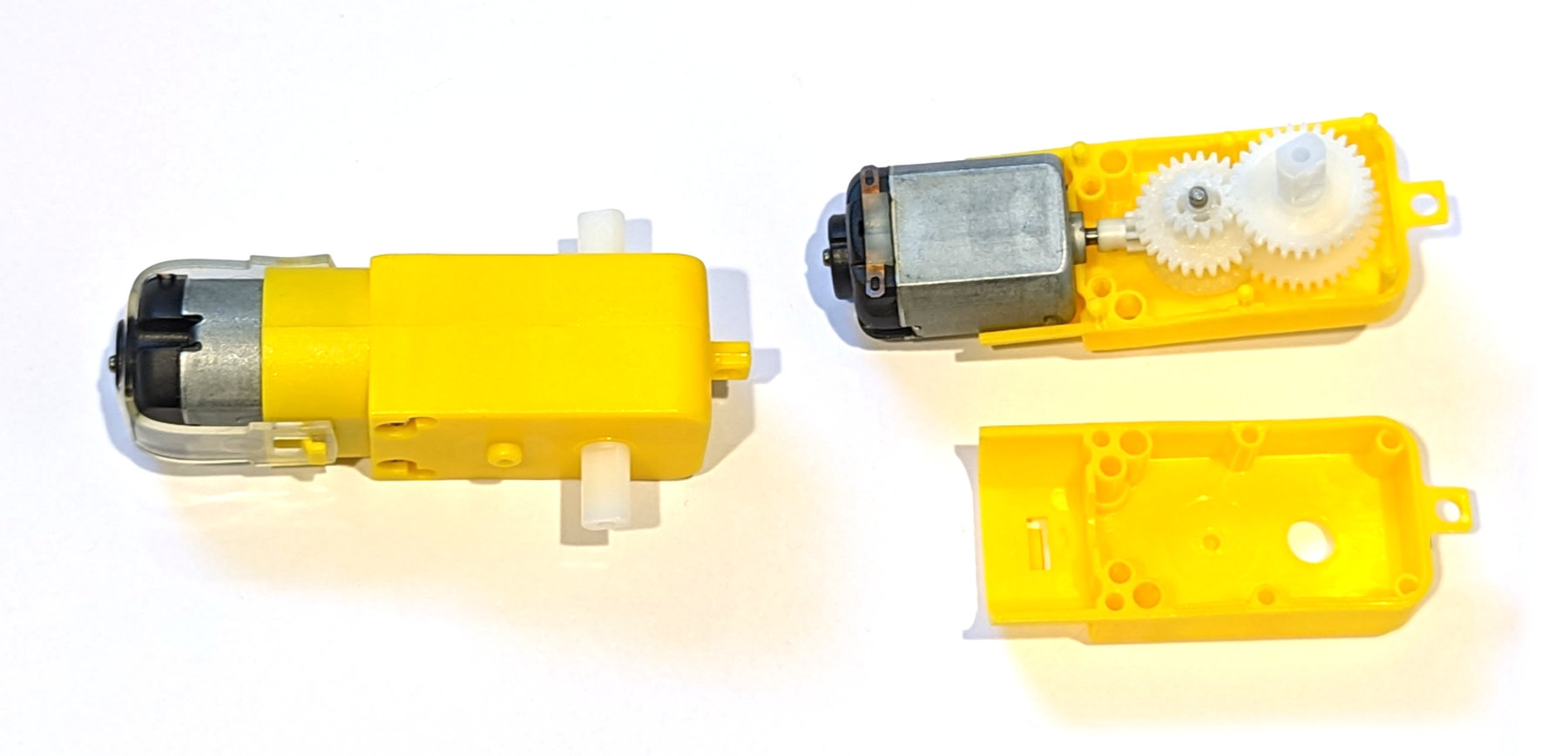
These motors can be operated with anywhere from 3v to 12V although the recommended range is from 3V to 9V. With 6V applied they will rotate at approximately 200rpm drawing 200mA. This is all assuming a ‘no-load’ condition where the motor is just turning it’s own shaft and not being put under strain (like driving a vehicle). When put under a load that resists the turning force of the motor it will draw up to 1.5A (at 6V) when forced to to a stall (stop).
Power
Running a motor takes a reasonable amount of current. Our Raspberry Pi Pico is not designed to pass significant amounts of current through it. The possible sources of electrical power from a Pico would be via either the VBUS (40) or 3V3 (36) pins.
- VBUS represent the micro-USB input voltage, connected to micro-USB port pin 1. This is nominally 5V, and the amount of current will be limited to the connected supply. While this might technically be a possible source, for power for a motor, it would only be suitable in situations where you were super careful about the type of motor and the USB power supply used. I wouldn’t do it and I don’t recommend it.
- The other option is from the 3V3 pin which is also the main 3.3V supply to RP2040. This pin can be used to power external circuitry, but the maximum output current that it can supply should be kept under 300mA. This is not realistically enough to power even a tiny DC motor.
In short, we won’t be taking the power supply for our motor from our Raspberry Pi Pico.
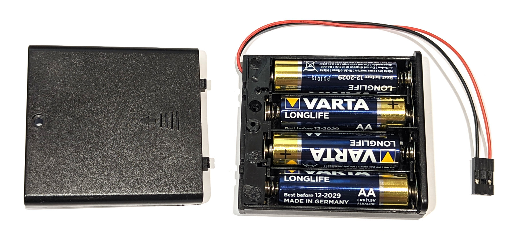
The sensible source for our power will be from an external battery or dedicated DC power supply. For the sake of simplicity we will use a simple 4 AA cell battery pack. This will be able to supply a voltage close to our 6V nominal identified for the motors. It should be able to supply over 1A, although running it under that much load for an extended period will reduce the voltage quickly)
If we were making this a stand-alone project (for a robot or vehicle), we would probably use this as the source for the power for the Pico as well (with a suitable regulator). Likewise, if this was for a project that was intending to be used a lot, we should consider some form of rechargeable option.
Controller / Driver
So from our requirements gathering process above we want to have a motor driver / controller that can supply two motors with a peak output of 1.5A per motor (just in case), it should be able to accept 6V input and in an ideal world it would act as a supply for our Pico with 5V out.
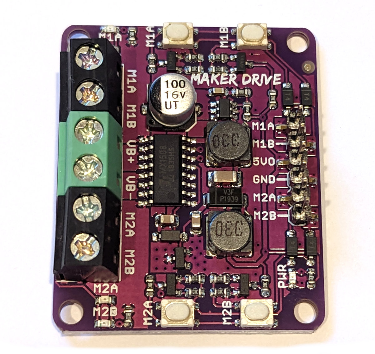
With these requirements in mind I have selected the Maker-Drive board from Cytron. It meets our requirements nicely and is very reasonably priced.
Types of Motion
There are two objectives that we will want to achieve with our motor control. The first will be simple movement forwards, backwards and stopped. The second will be to adjust the speed of any movement.
Simple movement
The simplest form of control is making our motor turn clockwise, anticlockwise or to have it stop.
Nost DC motor controllers will use two control signals to accomplish this. Either control signal can be high or low and therefore, any combination of the two will provide us with with four different signal combinations.

As we can see form the table above, whenever any of the two signals are both high or both low the motor will be stopped and whenever the signals are different it will be rotating.
Variable Speed
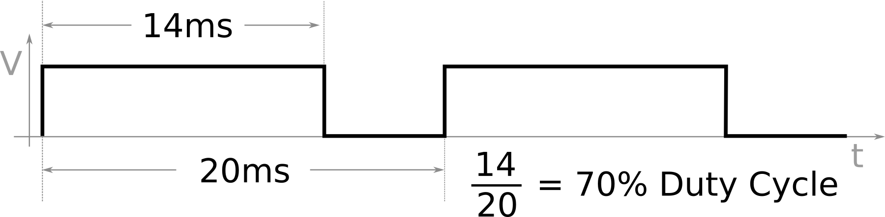
To vary the speed of our motor we need to apply Pulse Width Modulation (PWM) to our control signals. When the motor is turning in the simple example above, one of the control signals is set low and the other high. To vary the speed we can ‘pulse’ (modulate) the high pin off and on very quickly so that when combined with a smoothing effect, the voltage will appear reduced to the motor. The way that we will control this voltage is by varying the ‘duty cycle’ of the pulses.
The duty cycle of a signal is commonly expressed at the ratio of the time that the signal is high compared to the total period of one cycle. Thus a 70% duty cycle means the signal is on 70% of the time but off 30% of the time.
In MicroPython (as we will see in the code that follows) the duty cycle can be set as a parameter called duty_u16 where it varies between 0 (0% duty cycle) to 65535 (100% duty cycle).
Connecting Up the motor controller and battery
Connecting up our various components is as much about following a logical approach as it is about keeping everything simple.
The battery pack has its positive and negative connections connected to the VB+ and VB- pins of the Maker Drive board
The motor is connected to the M1A and M1B screw in connections on the Maker Drive. This will send the voltage out to the motor. It doesn’t matter which way round you connect the wires to the motor as it will be difficult to determine which direction the motor will turn before you test it. The rule of thumb here is that we will connect up our motor and test it and then change the connection if it is turning in the wrong direction.
The Pico has two PWM connection enabled pins connected (every GPIO pin can be configured as a PWM output) to the Maker Drive M1A and M1B header pins. In the case of the diagram below we are using GPIO pins 4 and 5 (physical pins 6 and 7). We also need to connect up a ground connector between the Maker Drive and the Pico.
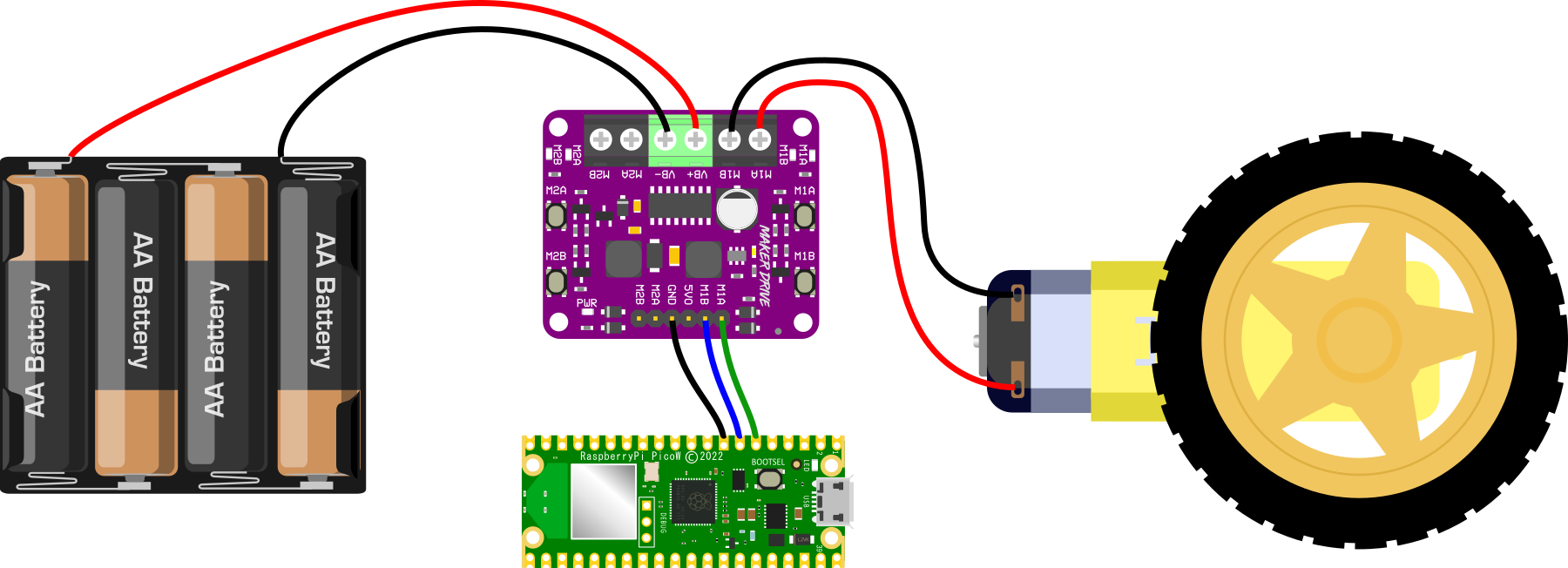
The connection above is assuming that we still have our Pico connected via USB to our computer for programming and testing. If we get to a point where we want to operate the Pico and the entire ensemble independently, we can also connect the Maker Drive 5VO pin to the VBUS pin (40) on the Pico and the Pico will take it’s power from the Maker Drive board which is in turn taking its power from the battery pack.
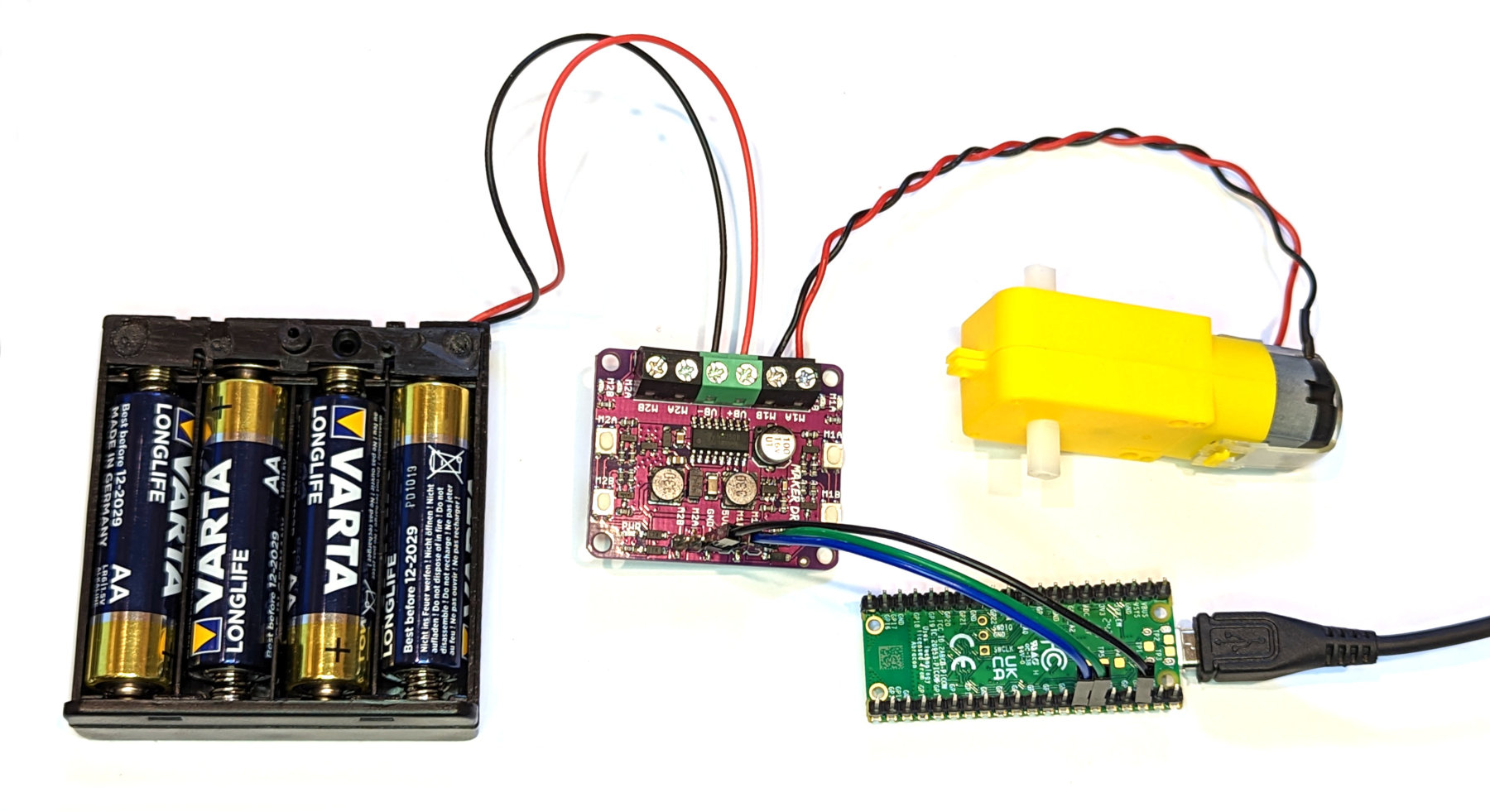
While the higher current connections to the Maker Drive board will go to the screw terminals, the connections that carry lower power (like the signalling) can be connected using Dupont connectors. A practical example of that can be seen below.
Code
The two different approaches to controlling the motors are outlined below.
Simple constant speed approach
The code below is a simple test which runs the motor forward and then backward for two second each way.
import time
from machine import Pin

motor1a = Pin(4, Pin.OUT)
motor1b = Pin(5, Pin.OUT)

# Forward
motor1a.high()
motor1b.low()

time.sleep(2)

# Backward
motor1a.low()
motor1b.high()

time.sleep(2)

# Stop
motor1a.low()
motor1b.low()
Variable speed demonstration
The code below is demonstrates the ability to vary the speed of the motor by using pulse width modulation on the signals.
import time
from machine import Pin, PWM

motor1a = Pin(4, Pin.OUT)

pwm_motor1b = PWM(Pin(5))
pwm_motor1b.freq(50)

# 1/4 speed
motor1a.low()
pwm_motor1b.duty_u16(16383)
time.sleep(2)

# 1/2 Speed
motor1a.low()
pwm_motor1b.duty_u16(32767)
time.sleep(2)

# FULL SPEED!!!!
motor1a.low()
pwm_motor1b.duty_u16(65535)
time.sleep(2)

# Stop
motor1a.low()
pwm_motor1b.duty_u16(0)
No comments:
Post a Comment