
Motion Sensing with the Raspberry Pi Pico
What is a PIR Sensor?
A passive infrared (PIR) sensor measures and evaluates InfraRed (IR) light emitted from nearby objects. They are referred to as ‘passive’ due to the fact that the sensor does not emit any heat or energy. Living animals emit infrared radiation and the sensor can pick this up and register it electronically. It uses a clever mechanism to detect a change in the infrared light it is receiving and as a result trigger a signal that can be read by an external device. In our case that will be a Raspberry Pi Pico.
PIR sensors are used in sensing applications, such as security alarms, motion detectors, and automatic lights.
I've written this short explanation as part of the much larger book 'Raspberry Pi Pico Tips and Tricks'. You can download it for free (or donate if you wish) from here.
How does a PIR Sensor Work?
Pretty much everything (humans, animals, even inanimate objects) emit a certain amount of infrared radiation. The amount relates to the body or object’s warmth and composition.
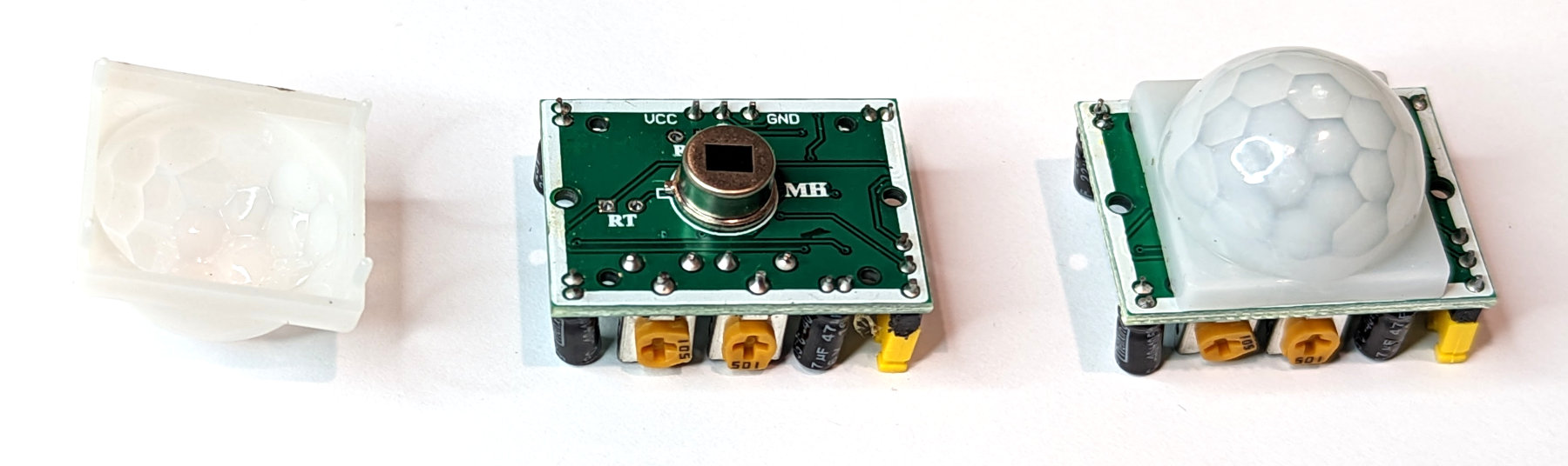
The PIR sensor proper is actually under the white hemispherical covering that is prominent on a PIR. The covering is in fact a lens that focusses radiation onto the sensor. The sensor has two slots in it where each slot allows infrared radiation to interact with pyroelectric receptors that are very sensitive to this type of emission at room temperature. The sensor is a hermetically sealed metal enclosure which improves immunity to noise, temperature and humidity. The sensor incorporates a window made of infrared-transmissive material for protection.
When there is no warm moving object in the sensors field of view it is idle and both slots detect the same amount of radiation. However, when a warm body like a human or animal comes into view, a signal is first detected by one of the pyroelectric sensors, which causes a positive differential change between the two halves. When the warm body leaves the sensing area, the reverse happens and the sensor generates a negative differential change. These changing pulses are what determines that movement has been detected.
The PIR sensor is mounted on a printed circuit board which supports the electronics that interpret the signals from the sensor itself. In a practical setting the complete assembly is usually contained within a housing which is located to provide a view over the area to be monitored.
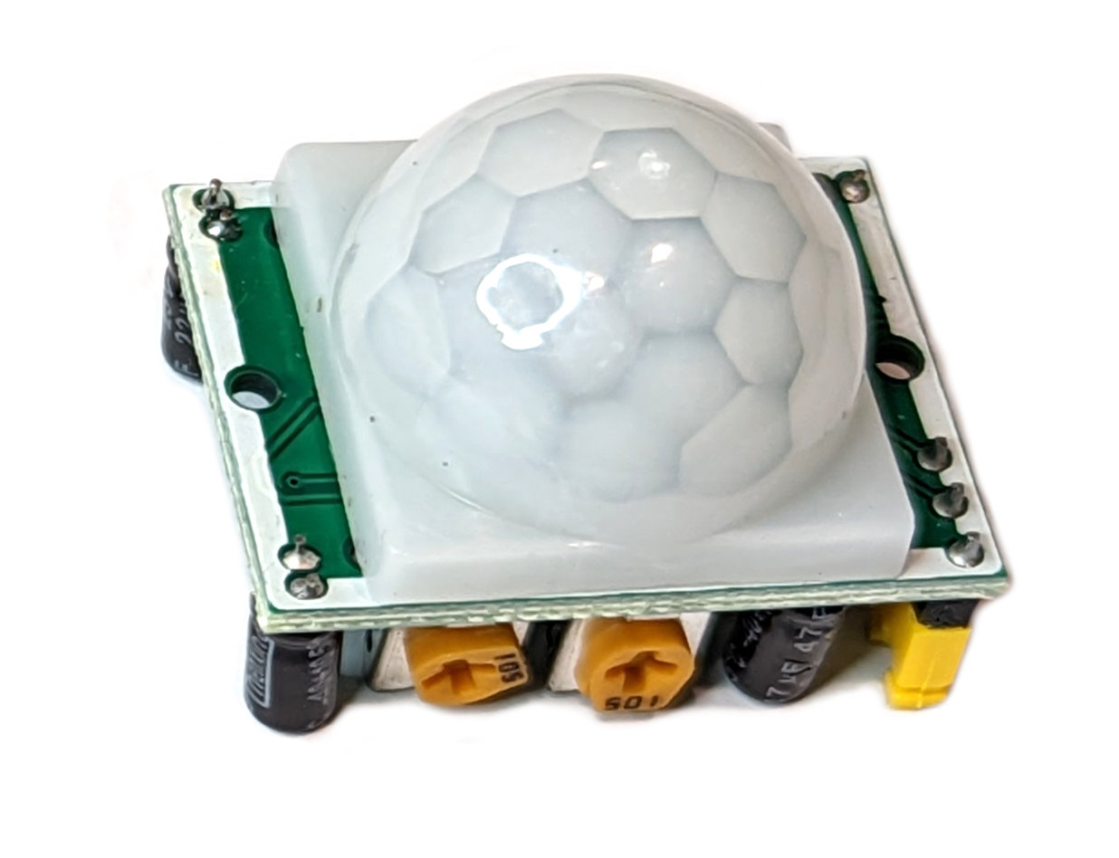
The white hemispherical lens is essentially a ‘window’ through which the infrared energy can enter. The plastic lens acts as a focusing mechanism which condenses a large area into a small one (in the same way that a camera lens works). To minimise the cost and size required the covering is normally a fresnel lens.
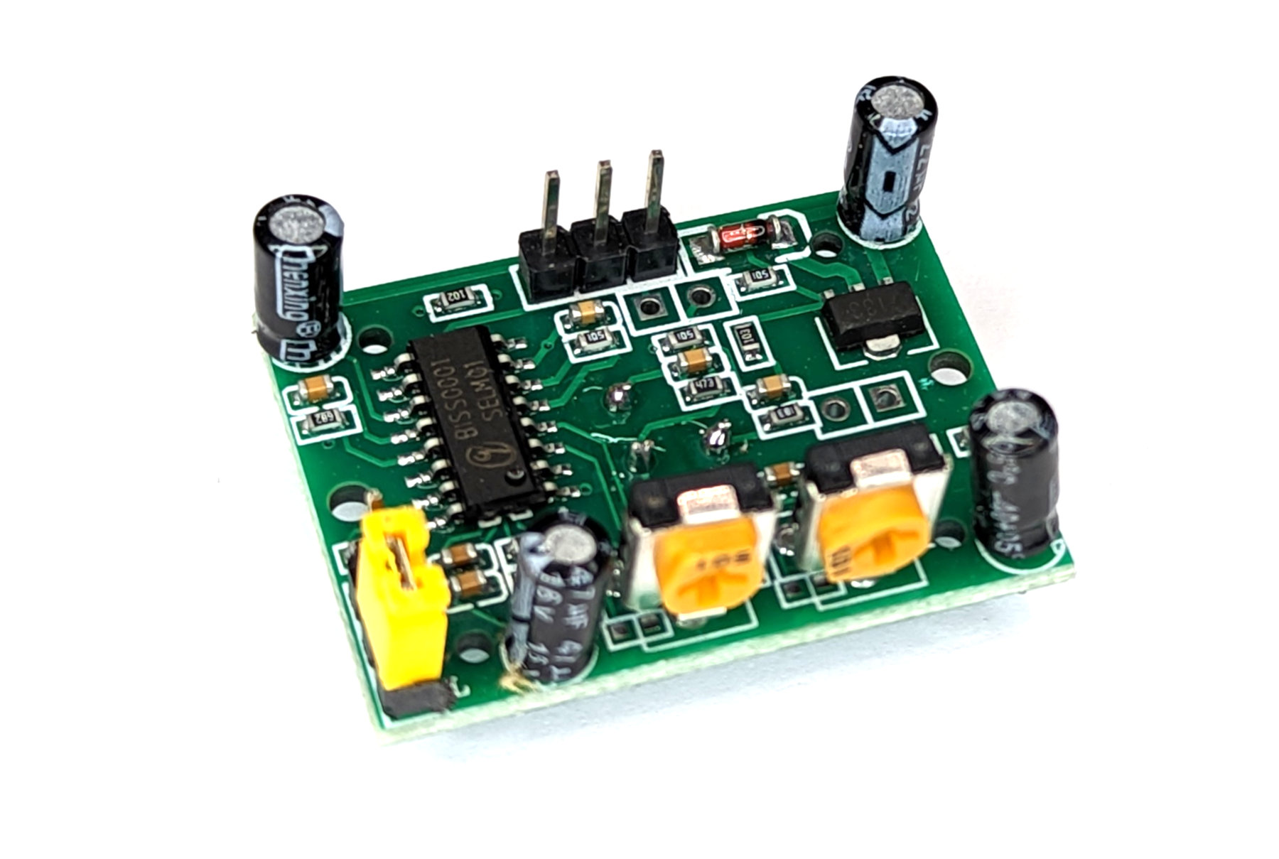
The HC-SR501
I’m including the HC-SR501 description here because I have a few hanging around and I had great plans to use one for a particular project involving a Raspberry Pi Zero some months ago. However, in the process of testing I found that it would trigger at times through interference with the WiFi signal on the Pi. This took quite a period to determine as I went through troubleshooting which included multiple sensors and different Pis. Ultimately I came to the conclusion that the analog portion of the design of the HC-SR501 that allowed the device to trigger unintentionally was not suitable for my application and I used the AM312 instead. That device uses digital signal processing which was unaffected by the WiFi signal.
The HC-SR501 has a 3-pin connector that interfaces it to the outside world. The connections are as follows;
- VCC is the power supply for HC-SR501 PIR sensor which we can connect a 5V pin.
- Output pin is a 3.3V TTL logic output. LOW indicates no motion is detected, HIGH means some motion has been detected.
- GND should be connected to the ground.
The HC-SR501 has a built-in voltage regulator so it can be powered by any DC voltage from 4.5 to 12 volts, typically 5V is used.
There are more than one model of this type of sensor. be careful to ensure that you have the connections correct. The best mechanism (other than following the labels if there are any) is to look for the protection diode as a reference. Failing that, if there aren’t any labels on the bottom of the circuit board, check on the board, under the lens.
There are two potentiometers on the board to adjust a couple of parameters;
- Sensitivity: This sets the maximum distance that motion can be detected. It ranges from 3 meters to approximately 7 meters. The layout of the area being covered can affect the range.
- Time: This sets how long that the output will remain high after detection is triggered. The minimum is 3 seconds and the maximum is 300 seconds or 5 minutes.
The board also has a jumper with two settings;
- H: This is the Hold / Repeat / Retriggering setting. In this position the HC-SR501 will continue to generate a high output while it continues to detect movement.
- L: This is the Intermittent or No-Repeat / Non-Retriggering setting. Here the output will stay high for the period set by the Time potentiometer.
As with most PIR sensors the HC-SR501 requires some time to adjust to the infrared environment that it sees in any room. This will take from 30 to 60 seconds when the sensor is first powered up. It also has a ‘reset’ period of about 5 or 6 seconds after making a reading. During this time it will not detect any motion.
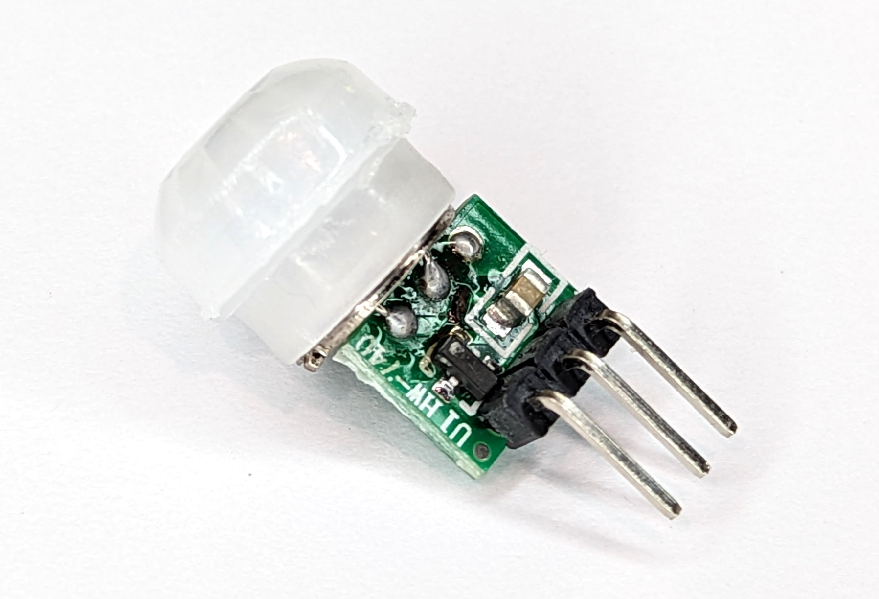
The AM312
As mentioned earlier, the AM312 utilises digital signal processing which removes one of the reasons that interference can affect the HC-SR501.
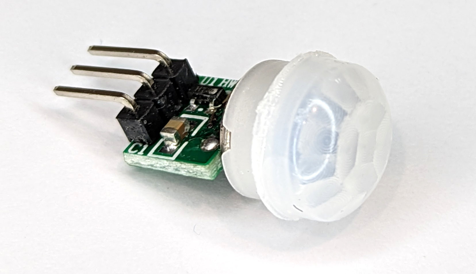
AM312 is described as a new digital intelligent PIR sensor! It is a much simpler and smaller device than the HC-SR501 with the digital detector and electronic circuitry built into the detector housing.
This sensor also has the advantage of being ultra-low power with a quiescent current of only 8uA making it suitable for battery applications where a very long battery life is required.
The pin connections are as follows with the orientation of the sensor with the header pins uppermost;
- Vin is the power supply which requires 3.3VDC.
- The Signal pin will present a high when motion is detected.
- Ground should be connected to the ground.

How do we read a PIR?
A PIR is one of the simplest sensors to read with the signal pin going high when motion is detected. This means that we can merely set any one of our GPIO pins to act as an input and then read when it goes high.
Connecting Up a PIR to the Pico
For the AM312 we can connect the sensor to the Pico as follows;
- Vin on the AM312 to the 3V3(Out) pin (36) on the Pico.
- Signal pin on the AM312 to GPIO 28 (pin 34) on the Pico.
- Ground should be connected to the GND pin (38) on the Pico
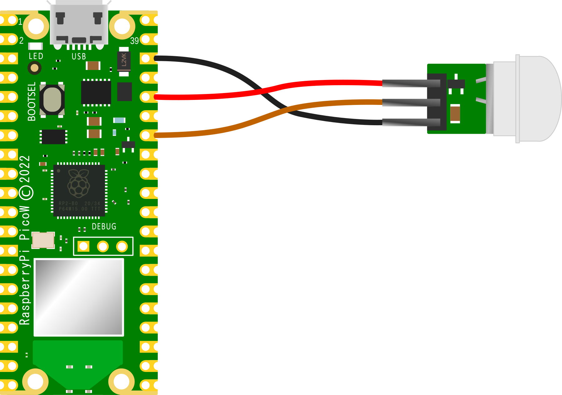
Connecting the PIR practically can be achieved in a number of ways. But because the connection is relatively simple we can build a minimal configuration that will plug directly onto the pins using Dupont header connectors and jumper wire.
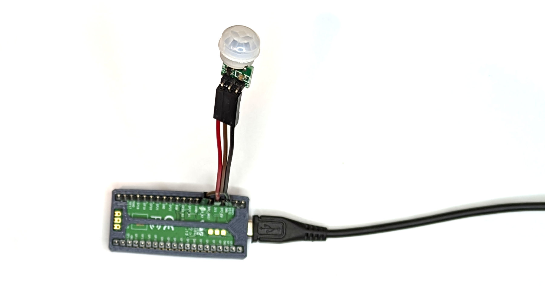
Be aware that there are a few similar models of this type of sensor. Be careful to ensure that you have the connections correct. The best mechanism (other than following the labels if there are any) is to look for the protection diode as a reference on the HC-SR501 and be aware that the diagram that I have shown here for the AM312 is shown with the header pins uppermost. For example the sensor I am using is not labelled, and the VCC and GND pins are in a different location to those shone on at least one connection diagram on the Internet.
Code
The code below will designate the GPIO pin to be used as our input (GPIO28) and set it low with a pull down resistor.
We can use any of the GPIO pins, so feel free to pick a convenient one. We use an internal pull down resistor to avoid having a ‘floating’ input. This will set the pin to be a logic 0 so long as it doesn’t have a signal applied.
It pauses momentarily to gather itself and then goes into an eternal loop where it prints out an alert when movement is detected. It also pauses after detection to give the detectors signal output an opportunity to return to a low state.
import time
from machine import Pin

pir = Pin(28, Pin.IN, Pin.PULL_DOWN)
count = 0

time.sleep(1)
print('Ready to detect movement!')

while True:
     if pir.value() == 1:
          count = count + 1
          print('Movement detected ', count)
          time.sleep(4)
     time.sleep(1)
No comments:
Post a Comment