
Pull-up and Puill-down resistors and the Raspberry Pi Pico
When setting up a GPIO pin as an input, it is important to provide a stable state at the pin to enable a reliable reading. It’s easy to simply think that this has to occur when an important event occurs like sensing a high level from a switch or when triggering from a pulse, but the reality is that a GPIO pin is looking for a reading of one of two states. We can call them a range of different things like;
- High and low
- On and off
- 3.3V and ground
- 1 and 0
Whatever we call them the important fact is that the signal level can be distinguished between two different states.
This means that when we want to register when a high voltage occurs on a pin, first we need to know what the low voltage is. And visa versa. If we are looking to try and read when a pin drops to ground, first the pin needs to be able to recognise the 3.3V is the high point.
We accomplish this feat of knowing our reference points by using pull-up and pull-down resistors on our Pico.
I've written this short explanation as part of the much larger book 'Raspberry Pi Pico Tips and Tricks'. You can download it for free (or donate if you wish) from here.
What does pull-up and pull-down actually mean?
The answer to the question is kind of in the name, but that doesn’t necessarily make it obvious. It’s also really useful to frame the question by using an example, and in our case (since this is being written for a book about the Raspberry Pi Pico) we can use a GPIO pin on the Pico as our case study.
We like to talk about our ability to read either a high or low signal on our GPIO inputs, but the reality is that there are three states that our voltage measuring effort could result in. A low state that will typically be ground or 0V, a high state that will typically be about 3.3V, and a mysterious third state which is ‘floating’.
We can illustrate this by attempting to measure the voltages on our Pico.
The low state
Using a meter to measure the voltage on our Pico, we can first ensure that there is a common reference point set by connecting our negative probe to a ground pin (here pin 23) and we can then measure the amount of voltage or potential difference is present between that ground pin and another (pin 33 shown here).
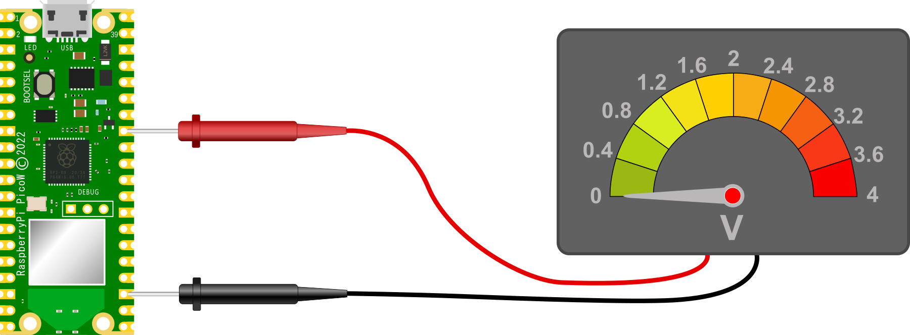
Unsurprisingly, we should read 0V. This is because the two ground pins are connected together on the circuit board and represent exactly the same voltage. Therefore the difference between them is 0V.
The high state
With our voltmeter measuring the difference between our common reference point of ground and the 3V3(OUT) pin (36), we are naturally going to read a voltage of 3.3V.
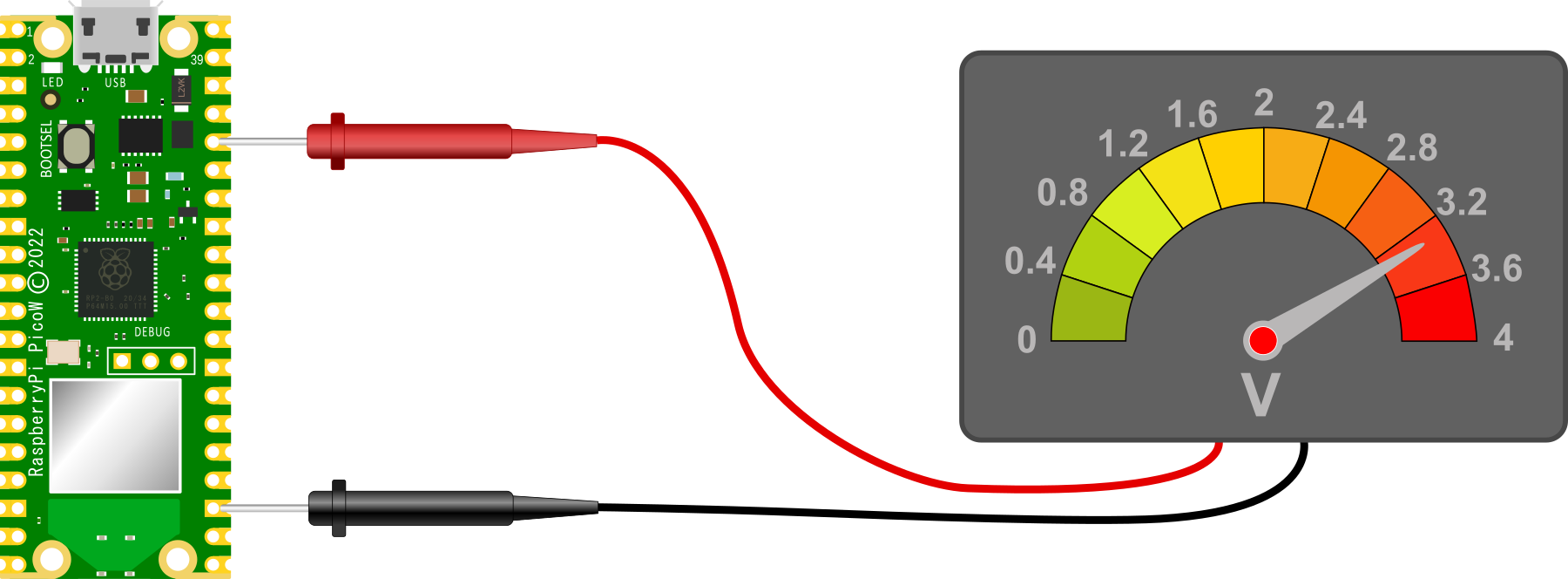
Again unsurprisingly we see 3.3V because there is a potential difference between the ground pin (23) and the 3V3(OUT) pin (36) of 3.3V
The floating state
And now to our ‘floating’ state. with our red lead removed from our Pico and floating in mid air, we have an uncertain reading on our voltmeter
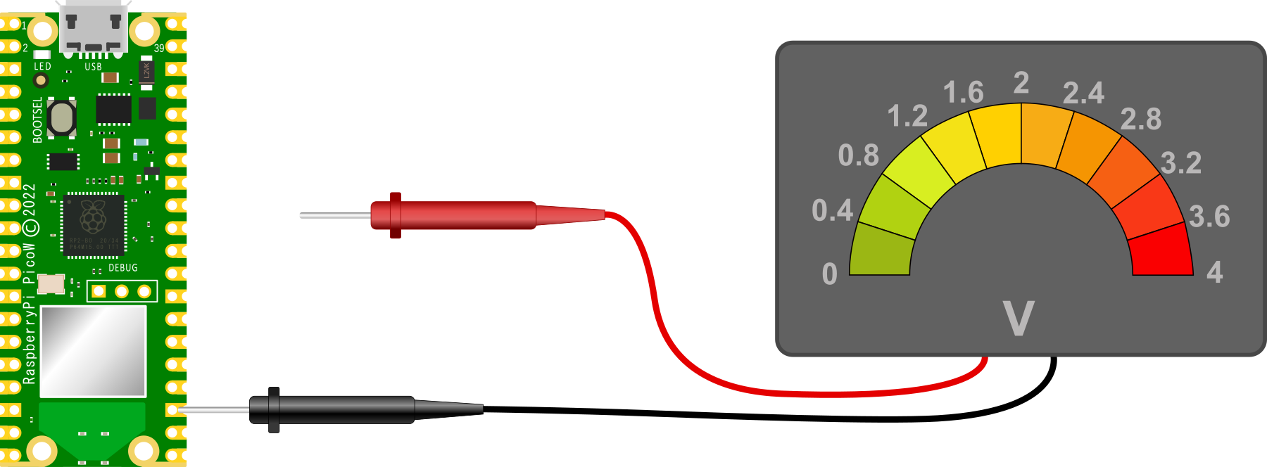
This situation is a bit like Schroedinger’s cat in the quantum state analogy. We can’t confirm if it’s alive or dead, so it’s both simultaneously. Except in this case, the reading is uncertain and we cannot state what it will be since there the meter is not fully connected to the circuit.
This floating state is the initial configuration of our GPIO pins on the Raspberry Pi Pico. Each one of them is essentially disconnected and as a result we can’t expect to read a steady voltage off them.
Pulling our pin
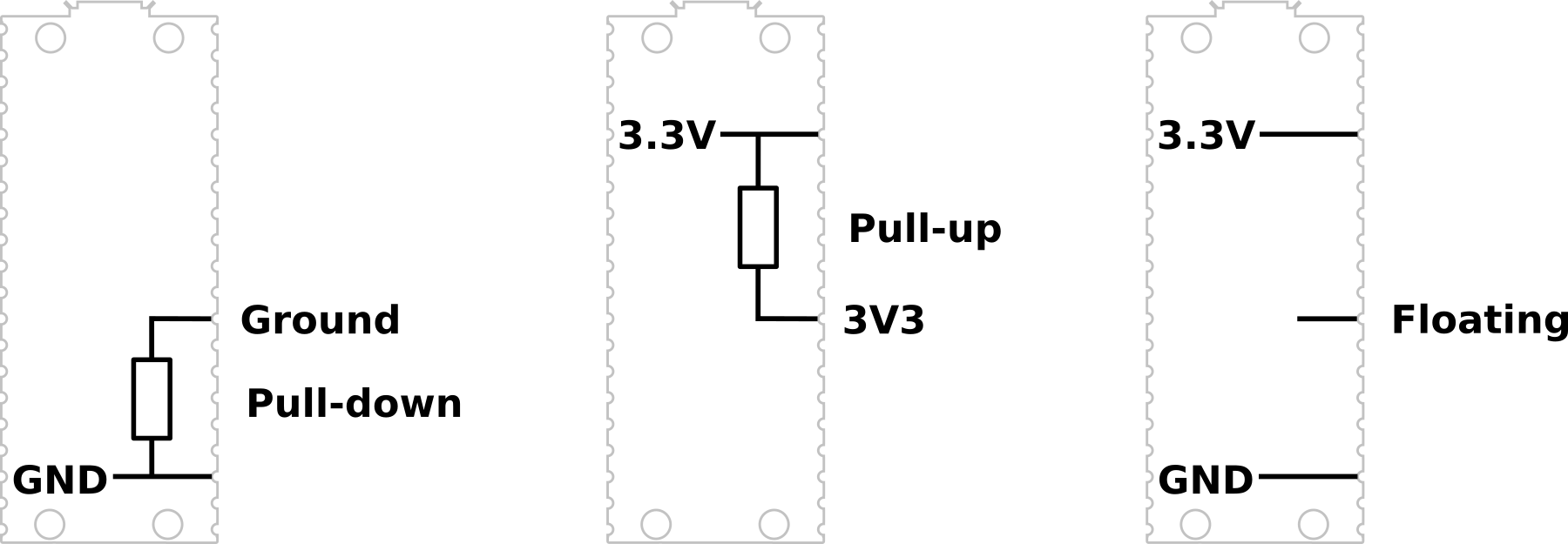
So to set our GPIO pins to a state where they have a reliable reference voltage we need to ‘pull’ the voltage either up or down so that in a resting state they read high or low.
A pull-up or pull-down resistor is connected so that the GPIO pin is connected to either ground or 3.3V via a resistance.
In some circuits this might be necessary to implement using discrete components, but the RP2040 microcontroller can configure a GPIO pin as either pull-up or pull-down internally and we just need to instruct it to do so via software. The resistance value in the pico is specified as being between a minimum of 50kΩ and a maximum of 80kΩ.
For example, in the PIR section of this book we set up our GPIO pin as an input and then we configured the pin as pull-down via the following code;
from machine import Pin

pir = Pin(22, Pin.IN, Pin.PULL_DOWN)
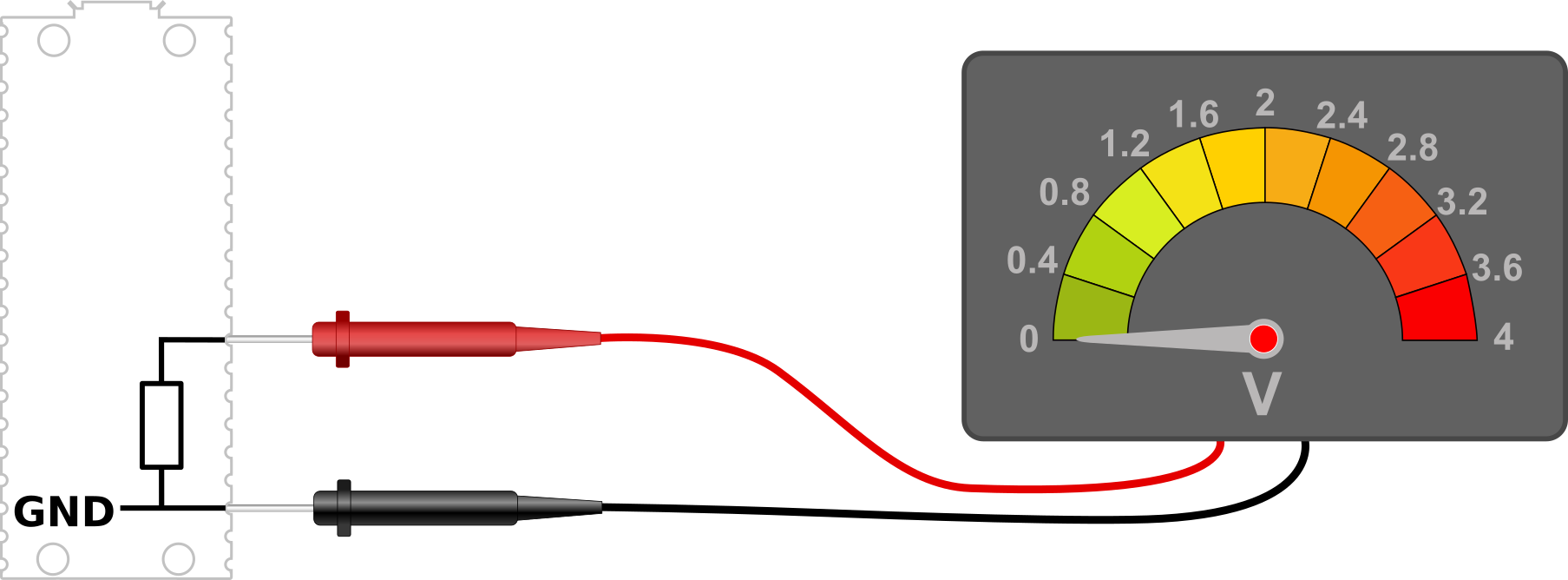
We can test our thinking by considering reading the voltage at our nominal GPIO pin with the Pin.PULL_DOWN configuration set. That will read 0V.
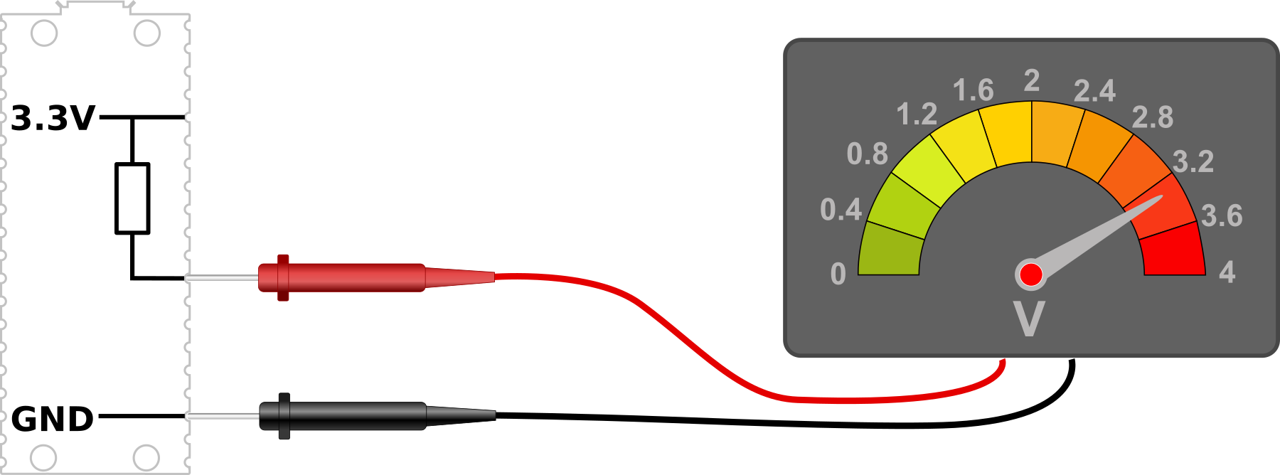
Conversely with the GPIO pin set to Pin.PULL_UP we will have the following circuit where we will read a voltage of 3.3V.
Once we have set the GPIO pin to its default state of high or low we can then go about the job of varying that pin to the alternate state via whatever input we choose. For example via a PIR or a common switch.
Don't forget, if you're looking for the book 'Raspberry Pi Pico Tips and Tricks'. You can download it for free (or donate if you wish) from here.
No comments:
Post a Comment