
Reed Switches with the Raspberry Pi Pico
Reading the state of a switch is a pretty basic function for a microcontroller, but it’s an action that is worth understanding and we can add a little bit of spice to it by using a switch that is commonly used in security systems and to detect the state of items that need to determine whether they are open or closed (fridges, laptops, washing machines).
I've written this short explanation as part of the much larger book 'Raspberry Pi Pico Tips and Tricks'. You can download it for free (or donate if you wish) from here.
What is a Reed Switch?
Reed switches are type of switch that are actuated via the presence of a magnetic field. They are typically constructed of two thin, flexible, ferromagnetic metal wires or blades (these are the reason that the switch is called a ‘reed’ switch). The blades are positioned slightly apart in a sealed glass tube. When it is placed in close enough proximity to a magnet that has enough strength to trigger the required level of actuation, the metal reed bends and the switch is made.
While this is a pretty cool type of switch, it’s function is the same as a wide range of other switch types from a standard push-button to a lever type to simply pressing two wires together. Basically it’s a way of connecting an electrical circuit.
The Magnetic Reed Switch
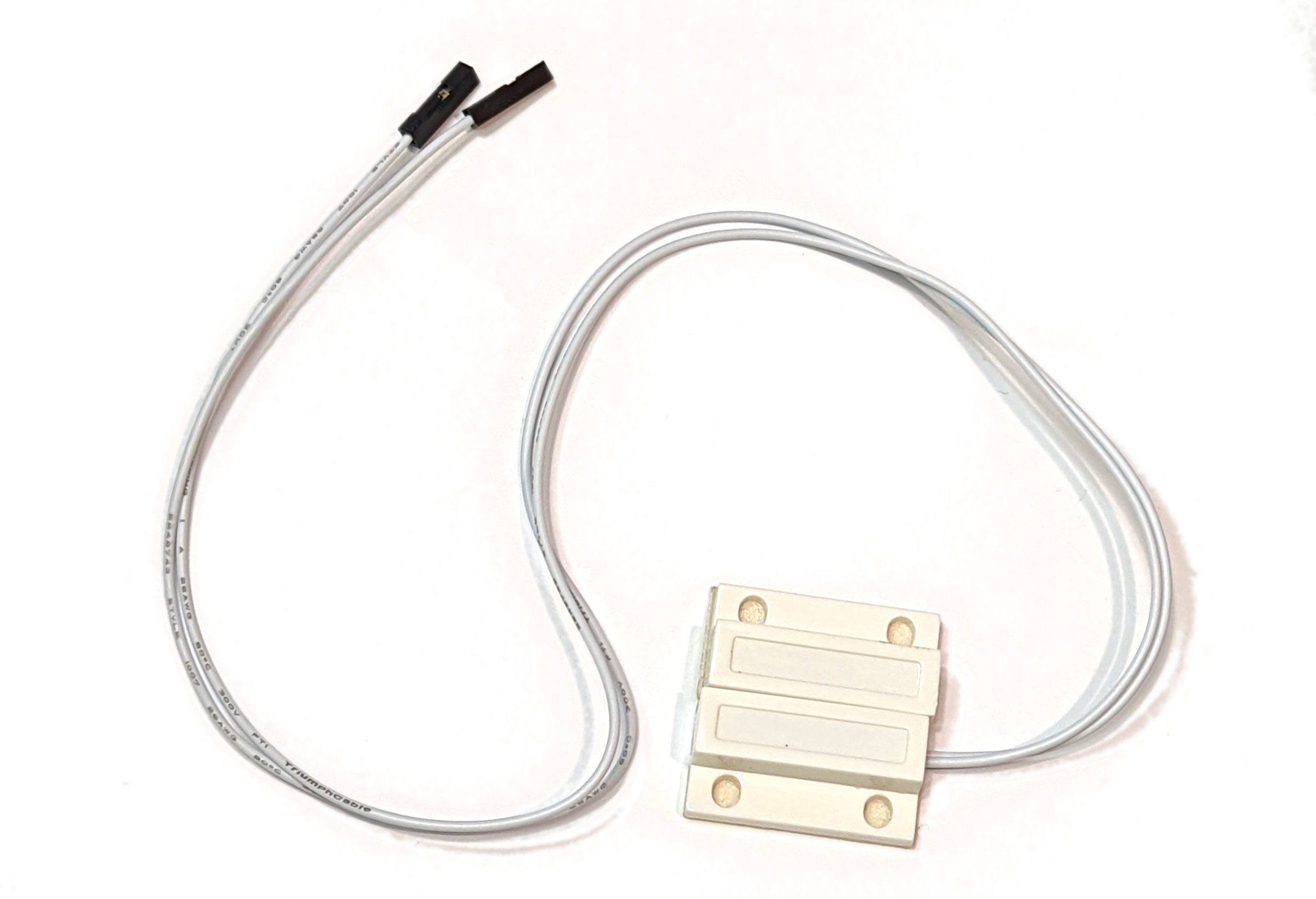
Our reed switch comes as the switch proper which is encased in a plastic mount with flying leads coming off it. In the picture that follows I have crimped two Dupont connectors onto the end of the leads for ease of connecting to the Pico. There is also a separate magnetic activator which, when moved close to the switch will enable it. I.e. we can imagine the portion with the leads mounted on a window frame and the magnetic activator portion mounted on the window proper.
How do we read a switch?
A switch is one of the simplest sensors to read. Once the input is configured in software, the two leads of the switch can be connected to the appropriate pins and we’re good to go. When the switch is made (or un-made) the state of the input changes and the Pico can read the input.
Pull-up or pull-down?
The main driver for the connection type is understanding what the switch is going to be switching. This might be dictated if you’re using a particular type of sensor, but for standard switch, we have two choices depending on whether we want to connect our switch to the 3.3V connection or the ground (the other end of the switch will be going to the GPIO pin).
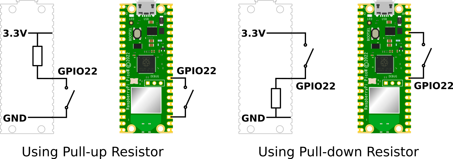
For a deeper explanation of how pull-up and pull-down resistors are selected and implemented in a circuit or a Pico, check out the section on pull-up and pull-down setting of GPIO pins earlier in the book.
If we’re connecting a simple switch, either method is as good as the other. However, I would normally opt for the pull-up option on the basis that it is easier to find a spare ground connector than it is to try and connect to the sole 3.3V pin.
With that in mind, the example that follows will configure our GPIO pin with a pull-up resistor and we will connect our reed switch between a ground pin (we’ll go for pin 23) and GPIO 22 (pin 29).
Connecting up the switch to the Pico
Because we are opting to use an internal pull-up resistor, we will connect our switch between a ground pin (pin 23 in this case) and GPIO22 (pin 29).
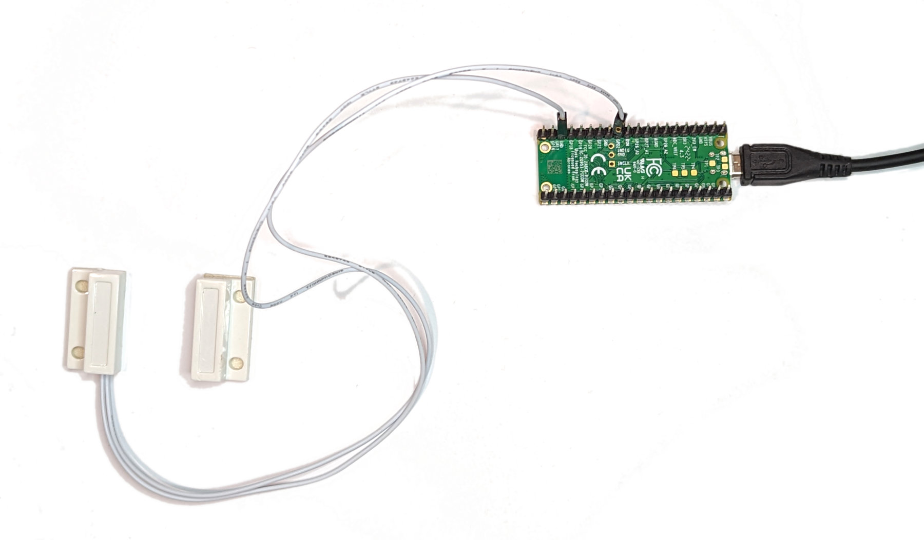
It makes no difference which way round the leads are connected.
Code
The code below will designate the GPIO pin to be used as our input (GPIO22) and set it to a default high state with a pull up resistor.
We will also need to set the GPIO pin to be an input (seen above as Pin.IN). Once set to input, the GPIO line is high impedance so it won’t draw very much current, no matter what we connect it to.
Our method to read the state of the switch is via the switch.value() parameter. Normally our GPIO pin will be high since our switch is a ‘normally open’ switch, but once the magnet is moved close to the main body of the reed switch, the mechanism closes, the switch is made and the GPIO pin is then connected to ground and reads 0V.
Just to make things interesting, it increments a counter and loops repeatedly incrementing when the switch is closed.
import time
from machine import Pin

switch = Pin(22, Pin.IN, Pin.PULL_UP)
count = 0

time.sleep(1)
print('Ready to switch!')

while True:
     if switch.value() != 1:
          count = count + 1
          print('Switch closed ', count)
          time.sleep(4)
     time.sleep(1)
No comments:
Post a Comment