
Using an OLED Display attached to a Pico
This project will use an attached OLED display unit to present information from our Raspberry Pi Pico.
I've written this short explanation as part of the much larger book 'Raspberry Pi Pico Tips and Tricks'. You can download it for free from here.
The OLED Display
The display that we’ll use in this example is based on the SSD1306 driver chip, which acts as a bridge between the display matrix and the Pico. The matrix can come in a variety of resolutions (128x64, 128x32, 72x40, 64x48) and colours (white, yellow, blue). The display itself uses an organic light-emitting diode (OLED) technology that allows it to be bright, fairly detailed and to have a wide viewing angle. It also doesn’t hurt that the device is also very reasonably priced.
The specifications of the unit used here is 0.96 inches on the diagonal, has a resolution of 128x64 and is white on a black background.
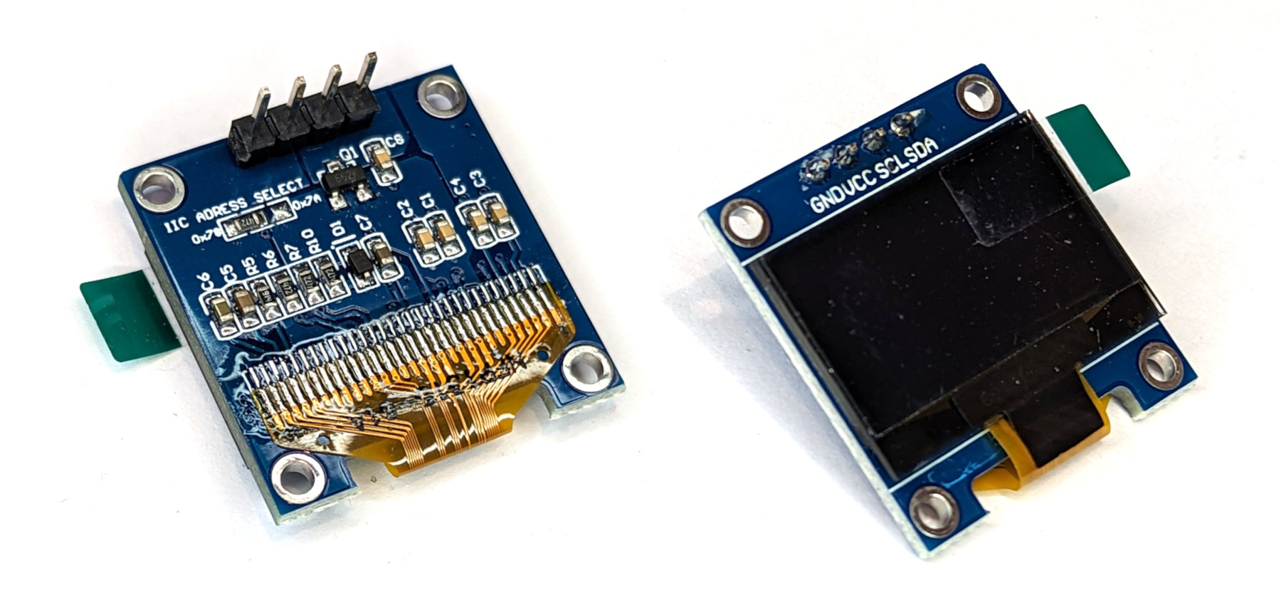
The green tab on the side is simply there to make removal of the protective film on the screen easy.
The SSD1306 micro-chip driver uses an I2C communications protocol and there is a PyPI library available that can be used for basic controls. There are some models that will also include SPI connectivity and these can be identified by having more than the four connecting pins that are shown on the model above. For more information on the unit we can consult the datasheet.
Connecting the Display to the Pico
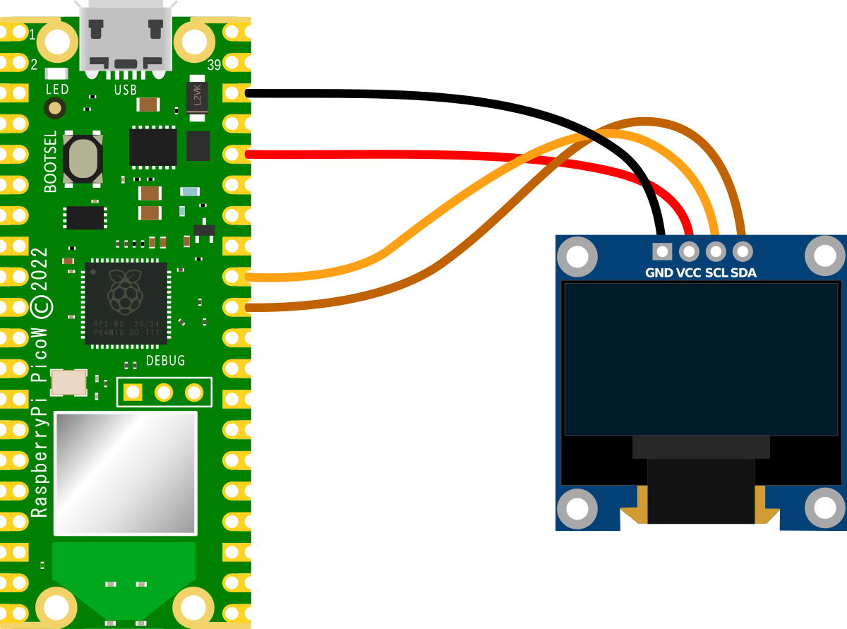
The connection is fairly simple with only four connecting wires being required. Power, ground, Serial CLock line (SCL) and Serial DAta line (SDA). The following connections are used for this example;
- Display GND to Ground (pin 38) on the Pico (Black)
- Display VIN to the 3V3(OUT) (pin 36) on the Pico (Red)
- Display SCL to I2C1 SCL (pin 32, or GPIO27) on the Pico (Orange)
- Display SDA to I2C1 SDA (pin 31, or GPIO26) on the Pico (Brown)
An important point to note when we are connecting our Pico is that because the RP2040 microcontroller has two I2C controllers, we need to ensure that we define which controller we are using in the code. I2C0 = id 0 and I2C1 = id 1. This is set in the following lines in the MicroPython code;
In our case, since we are using GPIO26 and GPIO27 for the SDA and SCK connections we are using I2C Controller 1.
Loading the ssd1306 PyPI module
The display is accessed via I2C, but we can abstract the complexities of this via a pre-built MicroPython library. To make use of the library we will use Thonny to find and download it.
- With our Pico connected to our desktop computer, open Thonny.
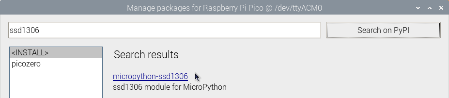
- Click on Tools > Manage Packages to access Thonny’s package manager.
- Type ‘ssd1306’ in the search bar and click on ‘Search on PyPI’. This will return a few results.
- Click on ‘micropython-ssd1306’ (ssd1306 module for MicroPython) and then click on ‘Install’. This will copy the library to our Pico.
Click on ‘Close’ to return to the main screen.
And that’s it, we’re all set up to use the ‘ssd1306’ library.
Code
The code below is incredibly basic and aimed at providing an example of how easy it it is to get started using the display. There is a great deal more that can be done with the display to add shapes, pictures and movement, but our aim is to get up and running and then from there we can push on to greater things :-).
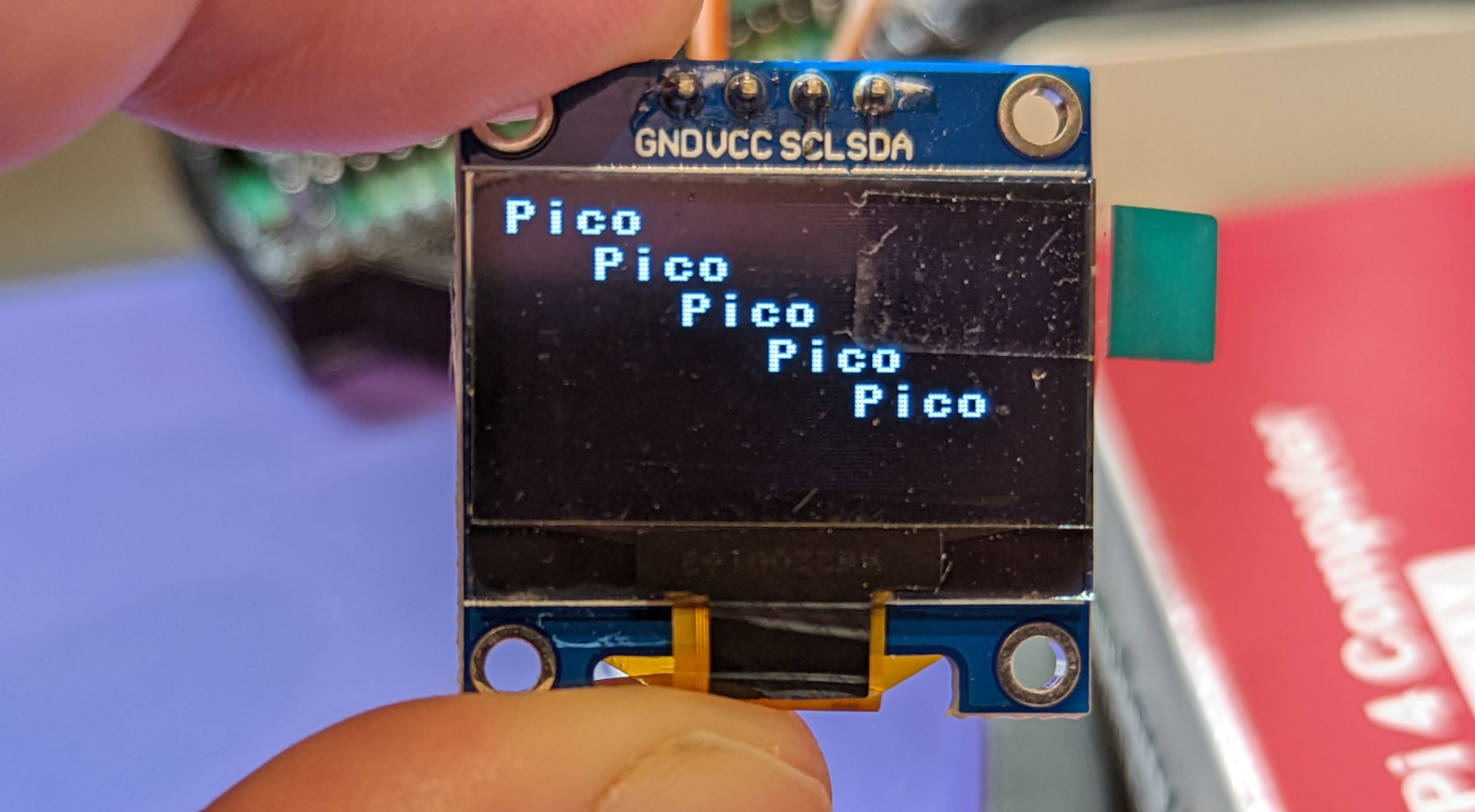
The code below will print ‘Pico’ five times staggered across the screen.
from machine import Pin, I2C
from ssd1306 import SSD1306_I2C

# Create I2C object
sda = Pin(26)
scl = Pin(27)
i2c = I2C(1, scl=scl, sda=sda, freq=400000)

oled = SSD1306_I2C(128, 64, i2c)

oled.text("Pico", 0, 0)
oled.text("Pico", 20, 10)
oled.text("Pico", 40, 20)
oled.text("Pico", 60, 30)
oled.text("Pico", 80, 40)

oled.show()
While the example above is limited, we can also use some of the code’s functions available for the display to add greater complexity. Feel free to have a play with some of the options below;
For greater illustration of what can presented on the display, check out the MicroPython docs page for the ESP8266 which presents further options.
And as a final tribute to the MicroPython instructions, run the following code;
from machine import Pin, I2C
from ssd1306 import SSD1306_I2C

# Create I2C object
sda = Pin(26)
scl = Pin(27)
i2c = I2C(1, scl=scl, sda=sda, freq=400000)

oled = SSD1306_I2C(128, 64, i2c)

oled.fill(0)
oled.fill_rect(0, 0, 32, 32, 1)
oled.fill_rect(2, 2, 28, 28, 0)
oled.vline(9, 8, 22, 1)
oled.vline(16, 2, 22, 1)
oled.vline(23, 8, 22, 1)
oled.fill_rect(26, 24, 2, 4, 1)
oled.text('MicroPython', 40, 0, 1)
oled.text('SSD1306', 40, 12, 1)
oled.text('OLED 128x64', 40, 24, 1)

oled.show()
Enjoy!
No comments:
Post a Comment